Continue to Site

Welcome to EDAboard.com

Welcome to our site! EDAboard.com is an international Electronics Discussion Forum focused on EDA software, circuits, schematics, books, theory, papers, asic, pld, 8051, DSP, Network, RF, Analog Design, PCB, Service Manuals... and a whole lot more! To participate you need to register. Registration is free. Click here to register now.

(another) help request - designing a filter for a DDS signal generator

Status
Not open for further replies.
S

slow_rider

Guest
Using an AVR, I implemented a simple DDS using an R/2R network. The output freq. I'm interested is up to 20KHz (since this is for audio usage).

Since my TL071 OA won't get near the lower rail I need to DC bias it using a non-inverting summing amplifier like this one (all 1M resistors):
summing-amplifier-non-inverting-configuration1.png


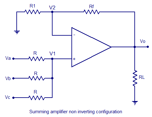
I have noticed that my sine wave is noisy so I added a low pass filter (I simulated a bunch and all work well) after the summing amplifier. However I get a side effect: When switching to square wave output I can see that the signal is getting trapezoid shaped. I am not sure why is that... Any help solving this would be appreciated (just a guess here - I am filtering out harmonics that make up the square wave).
 
Last edited:

Several points:
1) When you say your sine wave is "noisy", do you REALLY mean that you are seeing the effects of sampling? That's the nature of the signal, and you might need to filter it, depending on your application. If your sampling rate is high enough, you won't need to filter it, since your ears will do the filtering in the audio spectrum.

2) A square wave is actually a sum of odd-harmonics. If you filter out those harmonics, you don't have a square-wave any more (as you've discovered). You can't have it both ways, but you might want to choose a different filter. What you PROBABLY want is a filter with a steep rolloff(--> high order) so you can set your cutoff frequency high enough to pass a 'reasonable' square wave, but also filter out the digitization noise.

If you want to pass a really sharp square wave through a low-pass filter, you're kind of out of luck. You need to establish exactly what your requirements are.
 

Barry, thanks for the reply.

1. Point taken. I don't know *exactly* what is the noise I see but from playing around with filters it seems like this is something pver 50KHz. This is off course, as you said, not something my ears are bothered with.
2. I suspected this is what goes on and I really can't have it both ways. I think I will use a simple analog switch to switch on the filter if needed at all (although this means adding another gain stage to recover the gain after the analog switch loss).
 

You shouldn't need another gain stage; what is this driving? You can get analog switches with pretty low resistance.
 

This won't really driving anything, expects to go into a JFET input amp.

By the way, I can see the square wave "turning bad" even after feeding it into a simple non-inverting buffer OA. How come?
 

What's the slew-rate of your opamp? What's it's frequency response? What's your signal amplitude? A rule of thumb is:

F=0.35/Tr

where F is the highest frequency component, and Tr is the rise time of the signal. So, for example, if you're looking for a 10 nS rise time, you've got to be able to handle 35 MHz.
 

Status
Not open for further replies.

Part and Inventory Search

Welcome to EDABoard.com

Sponsor

Back
Top