iVenky
Advanced Member level 2
- Joined
- Jul 11, 2011
- Messages
- 584
- Helped
- 37
- Reputation
- 76
- Reaction score
- 35
- Trophy points
- 1,318
- Location
- College Station, Texas
- Activity points
- 6,124
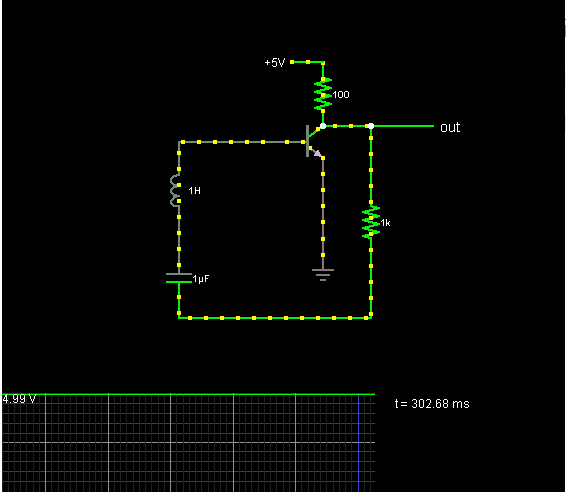
I have an inverting amplifier and in the feedback path I have a series combination of inductor and capacitor and Resistor
Then the transfer function of the feedback part is sL + 1/sC +R.
So that the 180 degree phase shift frequency is given by
tan-1( img/real) = 180
=> img/real=0
=> img part to zero
so that wL - 1/wC=0
so that
frequency w = 1/sqrt(LC).
Also if the amplifier gain is quite large then A* beta seems to be greater than 1.
But the truth is that it doesn't oscillate. Why is that so?.I know that I am missing something basic.
Thanks in advance.