Continue to Site

Welcome to EDAboard.com

Welcome to our site! EDAboard.com is an international Electronics Discussion Forum focused on EDA software, circuits, schematics, books, theory, papers, asic, pld, 8051, DSP, Network, RF, Analog Design, PCB, Service Manuals... and a whole lot more! To participate you need to register. Registration is free. Click here to register now.

Sinewave inverter prototype...

Status
Not open for further replies.

DeepOne

Advanced Member level 2
Joined
Feb 26, 2011
Messages
632
Helped
99
Reputation
200
Reaction score
100
Trophy points
28
Location
45N39E, Russia
Activity points
0

Picture of the signal from asynchronous engine 220V/50Hz around 30W power, connected to this scheme.
 

Attachments

  • svv.zip
    2 KB · Views: 1,277
Last edited:

Re: Sinewave inverter prototype.

Hi DeepOne,

Can You tell me what is the standby current of this inverter ?
 

Re: Sinewave inverter prototype.

Hi Tpetar.

Standby current at 12V line is around 100mA, at +310V depends on capacity of the output filter - when it is used input filter taken from PС PSU standby current is around 30mA.

Probably it is possible to slightly simplify scheme.
 
Last edited:

Re: Sinewave inverter prototype.

you used optocoupler as mosfet gate drive right? is it possible to use pulse transformer to isolate the mosfet? Optocoupler circuit is bulky. Did you face any problem with optocoupler?

- - - Updated - - -

didnt you generate pwm from atmega8?
 

Re: Sinewave inverter prototype.

is it possible to use a pulse transformer to isolate the mosfet?
I think yes, but for this modulation it is not so simple.

did you face any problem with optocoupler?
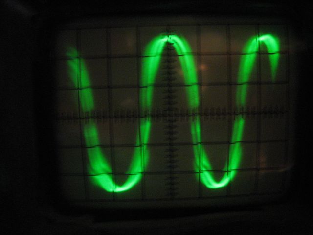
Optocouplers are usually not perfect in work with very short pulses, in consequence of which sinewave are little distorted.

didnt u generate pwm from atmega8?
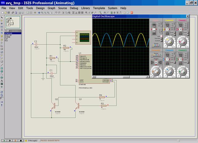
atmega8 generate pwm and signals to switchings.

else possible to try this schematics
 
Last edited:

Re: Sinewave inverter prototype.

good day. where is the schematic of 310 volts generation?
 

Re: Sinewave inverter prototype.

good day.

but for experiments I simply use rectified voltage from 220V network
 
Last edited:

Re: Sinewave inverter prototype.

possible to try to do another thereby schematics
 
Last edited:

Re: Sinewave inverter prototype.

possible to try to do another thereby schematics

I will try the DC-DC converter first. i will post the finish product soon. many thanks and credit to you. :)

my only problem is the transformer. by the way no harm in trying.
 

Re: Sinewave inverter prototype.

my only problem is transformer.
For such schemes this is not big problem. For instance it is possible take transformer from unused PC PSU (based on half-bridge schematics) and use low voltage winding as primary (or, better rewind it). Also, since air gap in ferrite core is not required it is possible take for base for that is approximately all anything. For instance i like to use ferrite cores from TV deflection system.

i will post the finish product soon.
there was interesting take a look so do not forget about this :).
 

Re: Sinewave inverter prototype.

hi DeepOne...

i try your post with proteus 7.8 but failed... the i try again with different transistor BC 817 replace BC 847 and then successful..but the sine wave clipped.

inverter.PNG

how solve the problem??
 

Re: Sinewave inverter prototype.

hi, Angga_steve90.

Possible deal in frequency with which microcontroller works.
Excuse me, in this moment i have no time. But if there is desire You can play with source code.
I have take for base code from pages https://my-avr.at.ua/publ/pwm_sin_na_atmega8/1-1-0-34
and little modified it.
 

Attachments

  • tmp.zip
    593 bytes · Views: 717

Re: Sinewave inverter prototype.

**broken link removed**

**broken link removed**


DC-DC- Conv Sch.jpg

this is my DC DC converter 12 vdc to 310vdc.

my only problem is the generation of 60hz sinewave.

do you have a analog circuit?

do you think the circuit of WPI pure sine inverter is working?

- - - Updated - - -

**broken link removed**

**broken link removed**


DC-DC- Conv Sch.jpg

this is my DC DC converter 12 vdc to 310vdc.

my only problem is the generation of 60hz sinewave.

do you have a analog circuit?

do you think the circuit of WPI pure sine inverter is working?

- - - Updated - - -

@Deep one

Hello. How are you? this is my 310VDC.

I'm now studying the PIC for 60hz sinewave generation. what do you think the best MCU for this project. i dont think if atmega8L is available in my country. :)
 

Re: Sinewave inverter prototype.

this is my DC DC converter 12 vdc to 310vdc.
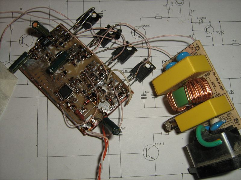
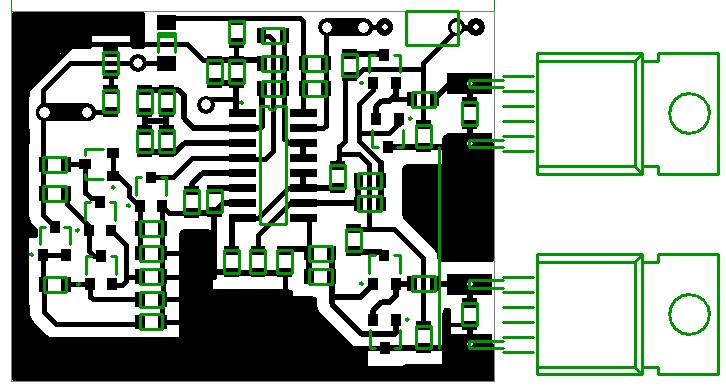
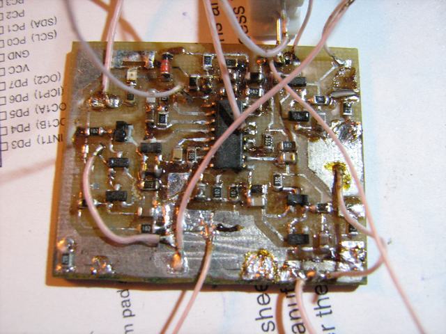
It is always pleasantly to see a real device )
do you have a analog circuit?
In general their exists enormous ensemble - for example, look on this pages - https://zpostbox.ru/g1.htm
But i think it is best to use specific chip, such as MAX038.
precision function generator producing accurate, high-frequency triangle,
sawtooth, sine, square, and pulse waveforms with a
minimum of external components. The output frequency
can be controlled over a frequency range of 0.1Hz to
20MHz
Or possible get pwm without microcontroller.


do you think the circuit of WPI pure sine inverter is working?
Why no? Question only in that - insofar well.
what do you think the best MCU for this project
Sorry, i do not know.
 

Re: Sinewave inverter prototype.

Good work Deepone
But I cant see the crystals and other fuse settings probabily you are using the internal ossc but for the fuses I cant guess. it will be more helpfull if you also put some light on it.

- - - Updated - - -

Good work Deepone
But I cant see the crystals and other fuse settings probabily you are using the internal ossc but for the fuses I cant guess. it will be more helpfull if you also put some light on it.
 

Re: Sinewave inverter prototype.

Good work
Thank you, but at this moment is not finished, may be when winter will come..

fuse settings - used internal 8MHz RC oscillator, other rest by default (hfuse=D9, lfuse=E4.
but i use AVRDude with suitable shell AVR_Burn-o-Mat).

Found else circuit, possible that is interesting for somebody.
 

Re: Sinewave inverter prototype.

I tried again with a different C is 0.01 uf, and the result is a sine wave with no cut off.

inverter sine wave.PNG
What software do you use to make the souce code?
you get to share the souce code for me??
 

Re: Sinewave inverter prototype.

For this project i use "CodeVisionAVR", but in my sight "MikroC" is more suitable due to suitable built-in functions.
you get to share the souce code for me??
Souce code attached in #13, for you and other to whom this can be interesting.
 

Re: Sinewave inverter prototype.

Carry on Dudes
Good to see knowledge and experimentation goes on. I think this scheme can also be used for those Modified/Square wave inverters as the out put can be converted in to DC and then Sine wave so the future is bright for this project and we can make it a near flaw less Gadget and the long and awaited Full sine wave dream can come true.
Any way thanks for lighting the first candle.

- - - Updated - - -

Carry on Dudes
Good to see knowledge and experimentation goes on. I think this scheme can also be used for those Modified/Square wave inverters as the out put can be converted in to DC and then Sine wave so the future is bright for this project and we can make it a near flaw less Gadget and the long and awaited Full sine wave dream can come true.
Any way thanks for lighting the first candle.
 

Status
Not open for further replies.

Part and Inventory Search

Welcome to EDABoard.com

Sponsor

Back
Top