Continue to Site

Welcome to EDAboard.com

Welcome to our site! EDAboard.com is an international Electronics Discussion Forum focused on EDA software, circuits, schematics, books, theory, papers, asic, pld, 8051, DSP, Network, RF, Analog Design, PCB, Service Manuals... and a whole lot more! To participate you need to register. Registration is free. Click here to register now.

programming problem in 7segment display

Status
Not open for further replies.

muttu.sarve

Junior Member level 2
Joined
Sep 30, 2011
Messages
20
Helped
0
Reputation
0
Reaction score
0
Trophy points
1,281
Activity points
1,465
hi every one..
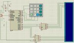
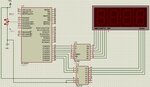
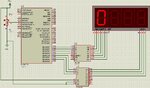
i'm facing some problem in my projects. i worked it on proteus and i have attached some snaps shot of my project. i'm reading analog i/p from RA2 and display it on 4 7-segments devices. i used 74ls78 bcd to 7 segment decoder and 74ls138 decoder. i've copied my source code too with this. the fig1 shows the intial setup and fig2 shows the during execution of the project. i think the problem with the code it self.. when i simulate in proteus only one device is active and its always shows zero (0) irrespective of analog input. i want to display the result on 7 segment so please go through the code and let me know if is there any changes have to make in this.
code:


Code C - [expand]
1
2
3
4
5
6
7
8
9
10
11
12
13
14
15
16
17
18
19
20
21
22
23
24
25
26
27
28
29
30
31
32
33
34
35
36
37
38
#include<16f877.h>
unsigned int cnt, brk;
char led [3];
unsigned int rem;
void converter (unsigned int z);
void scanled (void);
void main()
{
 OPTION_REG=0x80;
 PORTA=0;
 TRISA=255;
 PORTD=0;
 TRISD=0;
 while(1)
 {
  cnt=ADC_Read(2);
  cnt=cnt*5;
  converter (cnt);
  scanled ();
  }
}
void converter(unsigned int z)
     {
      led[0]=z/1000;
      rem=z%1000;
      led[1]=rem/100;
      rem=rem%100;
      led[2]=rem/10;
      led[3]=rem%10;
      }
void scanled (void)
     {
     unsigned char i;
     for (i=0;i<4;i++)
         {
         portd=i;portd=led[i];delay_ms(10);
         }
     }


Attachments

  • fig1.JPG
    fig1.JPG
    74.6 KB · Views: 92
  • fig2.JPG
    fig2.JPG
    110.9 KB · Views: 83
Last edited by a moderator:

your are using 74ls48 instead of the 74ls78 right?

char led [3];
should be
char led [4];

portd =i;portd=led;delay_ms(10);
should be
portd = (i << 4) | led; delay_ms(10);

note: functional correction on last update to this post
 
Last edited:

thank you for replying.. yes i'm using 74LS48. i changed the code as u suggested but it still giving same problem. please help me out in this one.
 

keep in mind that the first post I've made had an error on the code... have you used the current above code?
 

funny.. yes i know.. please let me know where i'm wrong in my code
 

I think there is a miss understood here... what I'm saying is that the first alterations to your code that I've suggested were wrong... I have updated that post... my question here is if you used the final corrections that I have made, witch are updated on the post above
 

ya.. i tried that too.. generate the hex code in mikro pro and dumped that hex file in my circuit that i built in proteus.. its still giving the same problem.. what would be the wrong thing in my code..
 

I think I got to know where is the problem... the delay is too short and human eye persistence is not working...

try this code:

Code C - [expand]
1
2
3
4
5
6
7
8
9
10
11
12
13
14
15
16
17
18
19
20
21
22
23
24
25
26
27
28
29
30
31
32
33
34
35
36
37
38
39
40
#include<16f877.h>
unsigned int cnt, brk;
char led [4];
unsigned int rem;
void converter (unsigned int z);
void scanled (void);
void main()
{
    OPTION_REG=0x80;
    PORTA=0;
    TRISA=255;
    PORTD=0;
    TRISD=0;
    while(1)
    {
         cnt=ADC_Read(2);
         cnt=cnt*5;
         converter (cnt);
         scanled ();
     }
}
 
void converter(unsigned int z)
{
     led[0]=z/1000;
     rem=z%1000;
     led[1]=rem/100;
     rem=rem%100;
     led[2]=rem/10;
     led[3]=rem%10;
}
void scanled (void)
{
    unsigned char i;
    for (i=0;i<4;i++)
    {
         PORTD = (i << 4) | led[i];  // corrected error  
         delay_ms(150);
    }
}


Also you should use a timer ISR to hop between the digits --- check this thread to know how to https://www.edaboard.com/threads/199354/
 
Last edited:

hello mgate, i tried your code o and i increased the delay time but still its having the same problem. and i didnt get know about ISR in that link.. i'm not getting its the code problem or proteus problem.. i simulate this in protues and i'm getting the following message.. check out the attachment.fig3.JPG
 

I don't know about the message but I had an error on the code ... I was writing portd instead of PORTD ... It is now corrected... sorry my bad.. FYI: you also did the same error twice in portd=i;portd=led;delay_ms(10); .. (I was making copy paste of your code :sad:)
anyway... feel free to test the above code
 

its my mistake sorry for that and thank you so much for your care about my code. i solved out that issue long back now the problem is as bellow.
there are two set of display. one 4 device 7segment is using to display the current count of adc output and another 3 device 7segment display which is to display the predefined count.. for example if i give 100(can be changed)count which is display on 3 device 7segment and the 4 device 7 segment willl count until it reaches 100 and it will show the output in 4 device 7 segment. i made the hardware arrangement for it.
i can connect another 3 display's segments to 74ls48 bcd to 7segments and with help of remaining pins in 74ls138 decoder i can manage to to connect those pins to common cathode pins of another 3 displays. can you please let me know how to solve this problem..
here is the schematic.. the 1st 4 digits in the display are used to display the count value which is read from adc and next 3 digits are used to display the user defined count number (like 100) and last digit is dummy in this schematic. the user define the count using keypad and which will display on 3 digit display then adc will start counting and corresponding display will come in 1st 4 digits of 7segment display.. when the predefined count will reach then the adc have to stop the couuting..

thank you :)
 

Attachments

  • fig4.JPG
    fig4.JPG
    138.3 KB · Views: 80
Last edited:

In code display handling its easy... All you need is a bigger char led[] array

replace:
char led[4];
char led[7];

use led[4],led[5],led[6] variables for the new dispay

also update for cycle in the scanled routine

void scanled (void)
{
unsigned char i;
for (i=0;i<8;i++)
{
PORTD = (i << 4) | led; // corrected error
delay_ms(150);
}
}
 

i already done it.. but its not working as i want.. i alter the code n combined with 4x4 keyboard code too.. as i told early user will enter the the 3 digit code which has to display on 3 digit display and adc will read from the input and it will count untill the user defined number and which has to display on 4digit 7segment display.. i think you not yet seen my previous post on the up..
 

I never used those keyboards, but they seem simple... will be hard to help without see the code you have
 

I never programmed PIC... If possible I would link PORTB 0-3 pins to a rising interrupt and handle keyboard input there
 

how it possible with only 4 pins. for 4x4 matrix keyboard it required 8 pins right??? if it possible then please let me know how can i program
 

how it possible with only 4 pins. for 4x4 matrix keyboard it required 8 pins right??? if it possible then please let me know how can i program

I say use only 4 pins on the Interrupt, because each keyboard button activates 2 wires right?.. to each line, or column, you only need one button to know that a button is being pressed... so I suggest an interrupt when a button is pressed.. then at the ISR you read the full 8 pins and parse the pressed button to an aux variable, raise a flag that button have been pressed... and let the main loop handle the button pressed
 

i agree with you. but i never done keyboard interface using interrupt.. can u please give a sample code for this so i can Analise and implement in my codes.
 

Status
Not open for further replies.

Similar threads

Part and Inventory Search

Welcome to EDABoard.com

Sponsor

Back
Top