Continue to Site

Welcome to EDAboard.com

Welcome to our site! EDAboard.com is an international Electronics Discussion Forum focused on EDA software, circuits, schematics, books, theory, papers, asic, pld, 8051, DSP, Network, RF, Analog Design, PCB, Service Manuals... and a whole lot more! To participate you need to register. Registration is free. Click here to register now.

[SOLVED] Leading onto Zeigler nichols technique

Status
Not open for further replies.

engineerme

Junior Member level 1
Joined
Apr 4, 2012
Messages
16
Helped
0
Reputation
0
Reaction score
0
Trophy points
1,281
Location
North east uk
Activity points
1,431
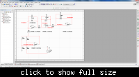
Hi, after previous help from a few very helpful members on edaboard (FvM and LvW) i have now got to a point that i am finding confusing. I have a circuit:


The gain at R6 was from an inital gain of 20db which produced a gain margin of -7.6756dB as shown in the AC analysis :


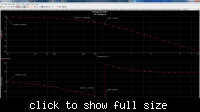
So gain required was 27.6756dB for stability, and into voltage gain = 24.198 (as shown in R6 against R5). By placing the voltage gain at R6 i produced an AC image that did not match up with -180 degrees.


Could anybody suggest what might be going wrong with my approach?
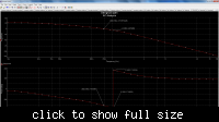
 

Hi,

I suppose you misunderstood the meaning of the gain margin.
The original circuit is stable with a gain margin plus 7.6 dB (because at -180 deg the gain falls below zero dB) - that means you have to increase the gain by 7.6 dB to reach the stability limit.

That means: Under these conditions (stability limit) your circuit - after closing the loop - is oscillatory since it meets the Barkhausen oscillation criterion.
After increasing the total gain by 7.6 dB do a TRAN analysis of the closed-loop circuit (small step input) and identify the oscillation frequency.
This is needed for the Ziegler-Nichols calculation.
 
Hi LvW,
Cheers. I thought thats what i did, the original gain was at 20dB (op-amp 1 set this already) to obtain a GM of -7.6dB, so a total gain of 27.6dB would create stability. But with the gain at this level, i did an AC analysis to which it did not line up with 180 degrees and it had another GM of different value (i wasn't aware of trans analysis after implementing GM, and it also applies to closing the loop). Cheers
 

Hi LvW,
Cheers. I thought thats what i did, the original gain was at 20dB (op-amp 1 set this already) to obtain a GM of -7.6dB, so a total gain of 27.6dB would create stability.

Two comments:
1.) Increasing the gain by the value of GM does not "create stability" - in contrary (as I have mentioned): You reach the stability limit.
2.) Opamp 1 (together with the input divider) has a gain of unity (0 dB)! Why do you speak of 20 dB?

---------- Post added at 19:00 ---------- Previous post was at 18:41 ----------

Additional comment: The original circuit (your diagram and the shown values) has a dc gain of 24.2 equivalent to 27.6 dB.
However, your simulation reveals a dc gain below 25 dB. Did you simulate with other component values?
 
Hi,

Right ok sorry its op-amp 2, 20dB is from the first active low pass filter (100k/10k). I do believe that my DC gain starts off at 27.4294 dB, il attach another:


I found that after implementing the GM and reaching the stability limit, the unity gain does not lie at the same frq. as my 180 deg phase response when i run the AC analysis again. I know that you mentioned before that increasing the gain by the GM factor would cause the loop gain to cross the 0dB line at 180 deg, indicating the frq. the closed loop would oscillate with, so i am only guessing at this point but, by using an open loop technique of analyzing my circuit i am therefore unable to run ac analysis for a closed loop analysis of my system, and would have to run trans with step response for closed loop analysis. My initial question relates to this, how can i show that my odB gain runs through 180 dB on a closed loop system? can it be done with AC analysis or is there a closed loop technique other than seeing the step response.

Dunk
 
Last edited:

Hi,
Right ok sorry its op-amp 2, 20dB is from the first active low pass filter (100k/10k).
I am sorry, but the circuit you have shown us contains no lowpass with a gain of 10. The 1st lowpass (opamp 1) has a gain of 24.2.

I found that after implementing the GM and reaching the stability limit, the unity gain does not lie at the same frq. as my 180 deg phase response when i run the AC analysis again.

What is your gain margin? You didn't mark it in the drawing. I can see that the PM is 25 deg. You have marked the crossing frequencies (which is not necessary), but what about the GM?

My initial question relates to this, how can i show that my odB gain runs through 180 dB on a closed loop system? can it be done with AC analysis or is there a closed loop technique other than seeing the step response.
Dunk

I repeat: After increasing the open loop gain by the value of the gain margin the open-loop magnitude crosses the 0 dB line at the 180 deg frequency. That's for sure.
If not - something is wrong with your circuit or with the simulation setup (see my very first sentence which points to some confusion in your postings).
Of course, you can do an ac simulation for the closed-loop case. Then you will see a very sharp peak (to infinity) at the oscillating frequency.
 
LvW,

The original low pass filter had 20dB (100k/10k) This was what i was talking about when i referred to the 20dB as you previously asked where did i get 20dB from. Since then i changed it to 241k/10k since the original GM was 7.6dB and the system had 20dB. At this point in time i have been trying to follow your advice, and i understand the concept of GM, to which i have tried to implement the required gain from the original GM within the first low pass filter DC gain (sorry if this is confusing), but i dont think my approach was correct, as you mentioned before something must be wrong with my circuit, to which i think i have a problem in understanding how to implement the required GM in my current set-up.

Dunk
 

OK, let's forget the previous discussion. There was some confusion on my side caused by your wording "first lowpass". You were referring to an older circuit (not shown in this thread) and I was of the opinion you mean the first opamp stage within the chain of four (first drawing in this thread).
Anyway - perhaps something went wrong with your previous simulations (gain of 20 dB).

Now - what I see is the following: Your last simulation still reveals a negative gain of X dB at the 180 deg frequency (unfortunately you have not marked the value of X).
That means: Open loop still shows a positive GM of X dB.
Therefore, further increase the gain within the loop by X dB and you will reach the stability limit (180 deg and magnitude of 0 dB at the same frequency.

Remark: If the input signal is applied as shown in the circuit diagram (post#1) the phase at small frequencies must be -180 deg and the stability limit at 0 deg.
Question: Does the simulation in post #5 NOT originate from the drawing in post #1 ?
 
Yes, both posts relate. Il start again and you can prob guess straight away whats going on. Circuit 1, no gain has been adjusted:


Circuit 1 AC image with gain margin of 7.6754dB:


Now at this point, the antilog of (7.6754dB/20) = Voltage gain of 2.419747. I am not sure where i can increase the gain on this circuit?

The only thing that i am not happy with is the AC injection, as i have put the - sign into the feedback loop, obviously with the thought that its negative feedback etc is this how you run an open loop AC injection ?
 
Last edited:

Ok i think i have solved the gain problem

AC analysis of 27.6757 dB:


This confirms what you were trying to get me to understand. Cheers LvW
 
Last edited:

Your motivation of dimensioning the circuit for zero gain respectively phase margin is still mysterious. Are you intentionally designing an unstable circuit?
 
Yes. I need to get to the limit of stability and show this on a graph for further Zeigler Nichols development. I could have shown this on a standard graph without changing the gain of the circuit (as you previously mentioned in another post-thank you). My mysterious drive for alterations to the circuit comes from helping me understand more about phase margins etc and the APPLICATIONS of GM.
 

I see. To demonstrate Ziegler-Nichols tuning methods, I would simply add a variable gain block.
 
variable gain block.

Interesting. How would you block gain? i can understand that having variable gain in a system would be beneficial, as the best i could get was two decimal places by adding the exact GM onto the previous system.
 

Interesting. How would you block gain? i can understand that having variable gain in a system would be beneficial, as the best i could get was two decimal places by adding the exact GM onto the previous system.

Hi engineerme,

I was absent for about 8 days - and after being back I have seen that your problem has been declared as solved. Fine.
Nevertheless, I think it could be beneficial for you to add some comments.
1.) The Ziegler-Nichols method for finding proper parameters for a PID controller primarily is aplicable to a control loop (hardware !) which consists of a plant with UNKNOWN system parameters. (This is in contrast to your task with a known transfer function of the plant to be controlled.). Such a system is forced to reach the stability limit (detected through oscillation behaviour) by introducing an additional gain block. The additional gain that is necessary to bring the closed-loop system to the stability limit is identical to the so called gain margin (GM). This value of GM as well as the resulting oscillation frequency is used to calculate the corresponding parameters for a suitable PID controller that replaces the additional gain block with the aim to create a "good" closed-loop behaviour (step response with an acceptable overshoot).
2.) At the beginning of your investigations it was your fault (and I must confess that I have noticed this error to late) to increase the gain of a low-pass filter thereby changing the phase response as well. But it seems that you have corrected this by introducing a separate gain stage.
3.) I think it is/was your task to test and verify the Ziegler-Nichols tuning method only via simulation. In this case, it is indeed not necessary to introduce the mentioned gain stage because the GM value as well as the potential oscillation frequency (180 deg frequency) can be identified based on the loop gain response only.
___________________

Perhaps this could improve your understanding.
Good luck
LvW
 
Cheers for your help LvW. It would be interesting to have a play with some hardware and an unknown system. How did you come across this experience, is it just principle electronics or have you had first hand experience of PID controllers?

At first i could understand that increasing the gain would cause the bode magnitude plot to just shift up, but me personally i think its good if you can apply things like this. However, by applying it the wrong way i have learned about what affects circuits like this one (DC control and phase response). Its confusing as hell when you look at something for the first time and don't know so much about the questions asked, but when you make mistakes i guess that's how you learn (I am a mechanical engineer). I have completed the open and closed loop Ziegler Nichols tuning methods, and found quite a few differences in the accuracy (one being that the closed loop method with step response requires you to draw a line of best fit to work out the time constant and process delay, to which the line of best fit had about 4% error, as opposed to open loop injection method which was quite accurate).


Duncan
 
Last edited:

Status
Not open for further replies.

Part and Inventory Search

Welcome to EDABoard.com

Sponsor

Back
Top