patdrige
Newbie level 2
Hi there
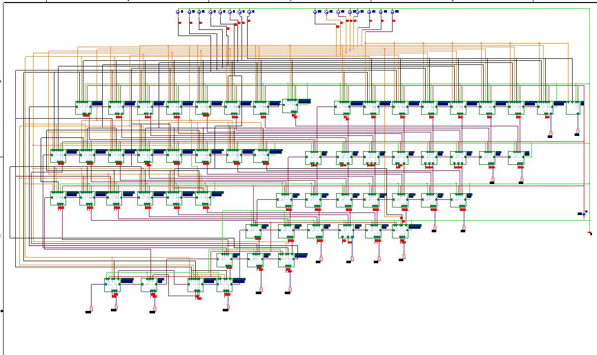
I need help on this ckt to to transient analaysis. I am getting the error . I have copied and paste the some of the similar error but there are more there i also have attached the pic of whole unit and a Individual unit. please help me why i cant get the transient analysis. My ckt has no error for sure.
thank you
ERROR -- Convergence problem in transient bias point calculation
Last node voltages tried were:
NODE VOLTAGE NODE VOLTAGE NODE VOLTAGE NODE VOLTAGE
( P0) 24.75E-06 ( P1) 34.58E-06 ( P2) 34.58E-06 ( P3) 34.58E-06
( P4) 34.66E-06 ( P5) -.2063 ( P6) .2518 ( P9) 34.58E-06
.........
Adder_N50023) 37.89E-06 (Adder_N50037) 16.93E-06
(Adder_N50111) 11.49E-06 (Adder_N50203) 35.68E-06
(Adder_N50219) 18.58E-06 (Adder_N50249) 26.23E-06
(Adder1_N50023) 38.18E-06 (Adder1_N50037) 16.99E-06
(Adder1_N50111) 16.17E-06 (Adder1_N50203) 35.75E-06
(Adder1_N50219) 18.62E-06 (Adder1_N50249) 26.47E-06
......
hese voltages failed to converge:
V(Adder18_N50203) = 601.23mV \ 627.10mV
V(N85109) = -690.41mV \ -874.50mV
V(Adder18_N50111) = -899.23mV \ -1.111V
V(Q46) = -328.02mV \ -306.49mV
V(Adder18_N50249) = -630.38mV \ -656.34mV
V(N84819) = 296.24mV \ 322.15mV
V(N84863) = -190.00mV \ 412.54mV
V(N85113) = 66.87mV \ 61.76mV
V(SUM8) = -905.65mV \ -67.78V
V(Adder18_N50219) = -690.42mV \ -874.50mV
V(Adder18_N50037) = -342.38mV \ -295.94mV
V(Adder18_N50023) = -......
These supply currents failed to converge:
I(V_V1) = 340.32nA \ -2.290uA
I(V_V2) = -37.31pA \ -67.84pA
I(V_V3) = -16.48pA \ -28.01pA
I(V_V4) = -14.39pA \ -25.70pA
I(V_V5) = -32.07pA \ -57.02pA
I(V_V8) = -3.928nA \ -6.559nA
I(V_V14) = 34.32pA \ 58.58pA
I(V_V17) = 5.268pA \ 9.223pA
I(V_V13) = 969.57pA \ 1.628nA
I(V_V10) = 31.52pA \ 55.24pA
I(V_V12) = 57.61pA \ 99.34pA
I(V_V15) = 5.856nA \ 9.63nA
These devices failed to converge:
M_Adder18_M4 M_Adder18_M8 M_Adder18_M17 M_Adder18_M3 M_Adder18_M7
M_Adder18_M13 M_Adder18_M1 M_Adder18_M20 M_Adder18_M9 M_Adder18_M6
M_Adder18_M12 M_Adder18_M15 M_Adder18_M5 M_Adder18_M11 M_Adder5_M8
M_Adder5_M17 M_Adder5_M13 M_Adder5_M1 M_Adder5_M20 M_Adder5_M12
M_Adder5_M19 M_Adder5_M5 M_Adder5_M11 M_Adder7_M8 M_Adder7_M17 M_Adder7_M3
M_Adder7_M7 M_Adder7_M1 M_Adder7_M20 M_Adder7_M6 M_Adder7_M12 M_Adder7_M19
M_Adder7_M11 M_Adder22_M4 M_Adder22_M8 M_Adder22_M14 M_Adder22_M3 .......
Attachments
Last edited by a moderator: