tnnedaboard
Member level 3
Hi,
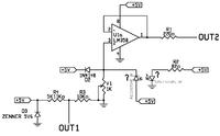
I found the following circuit that reads the skin phototype. I assume that uses the principle of refraction. The amount of signal emitted by the IR transmitter reflected from the light skin is different from that reflected from dark skin. So the IR receiver will give different values depending on whether the skin is lighter or darker. These voltage values appropriately interpreted by a microprocessor, are translated into phototype 1 (light skin) to skin type 5 (dark skin). I got the wiring diagram:
I have the following questions:
- What is the function of OUT2 (suitably amplified and connected to the microprocessor)?
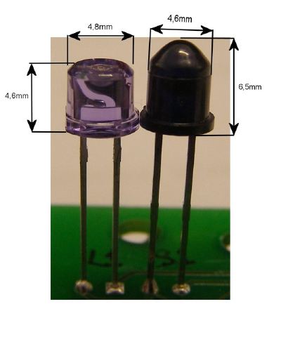
- What kind of IR transmitters and receivers are used? (See photo)
Best Regard
I found the following circuit that reads the skin phototype. I assume that uses the principle of refraction. The amount of signal emitted by the IR transmitter reflected from the light skin is different from that reflected from dark skin. So the IR receiver will give different values depending on whether the skin is lighter or darker. These voltage values appropriately interpreted by a microprocessor, are translated into phototype 1 (light skin) to skin type 5 (dark skin). I got the wiring diagram:

I have the following questions:
- What is the function of OUT2 (suitably amplified and connected to the microprocessor)?
- What kind of IR transmitters and receivers are used? (See photo)
Best Regard