Vermes
Advanced Member level 4

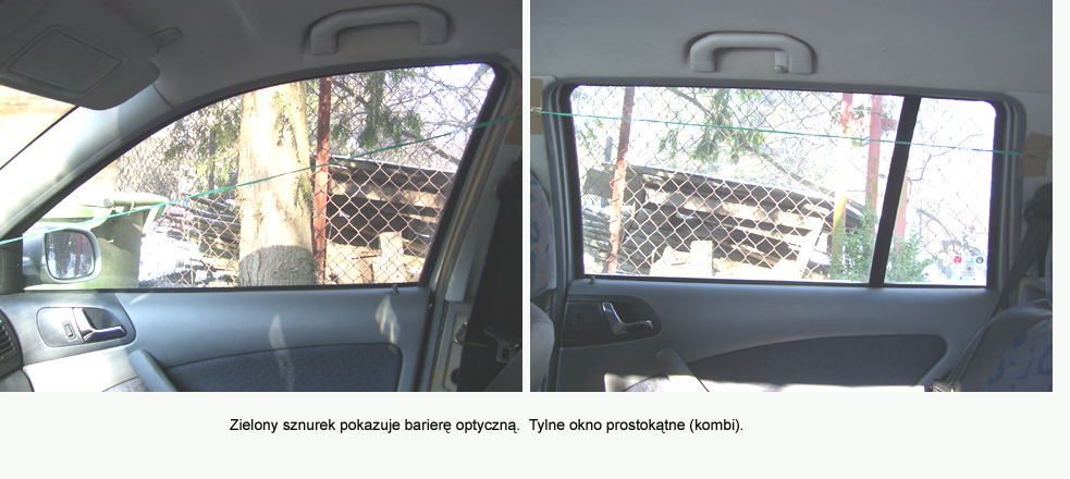
Most cars are equipped with overload protection in electric window elevators, causing switching off the motor when raising window encounters an obstacle, but it can be too late and our hand can hurt. Optical barrier can be used to avoid unpleasant effects of being „caught” by a window. You do not need a complicated system which controls the engine, everything is done without a touch and knowledge of the user, and what is the most important – the protection is very effective. It works even when a head or a hand is close to the window.
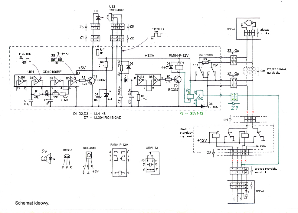
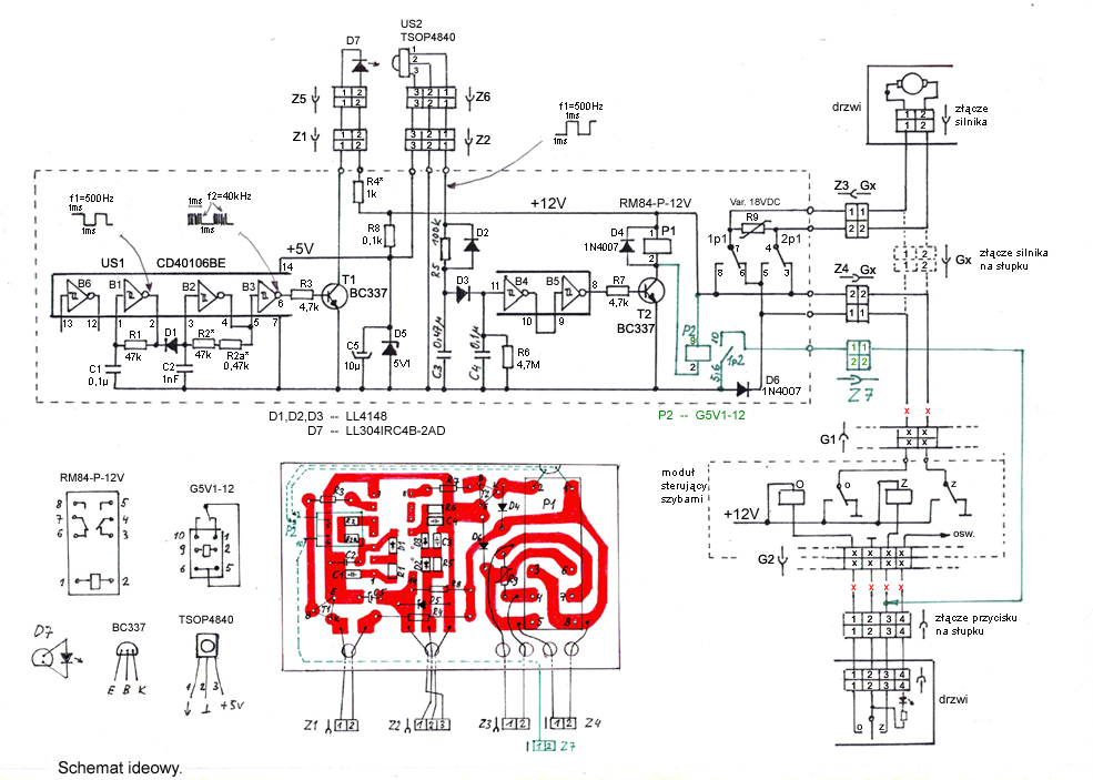
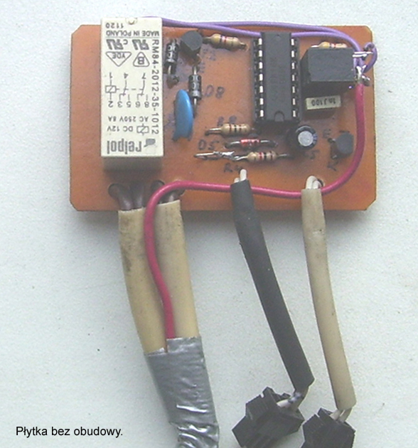
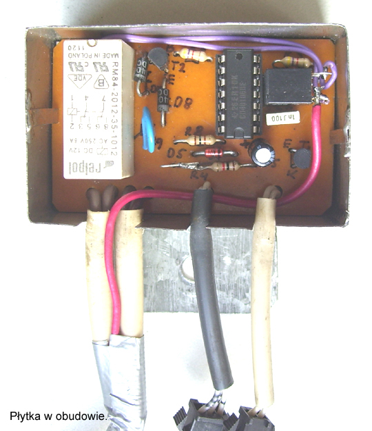
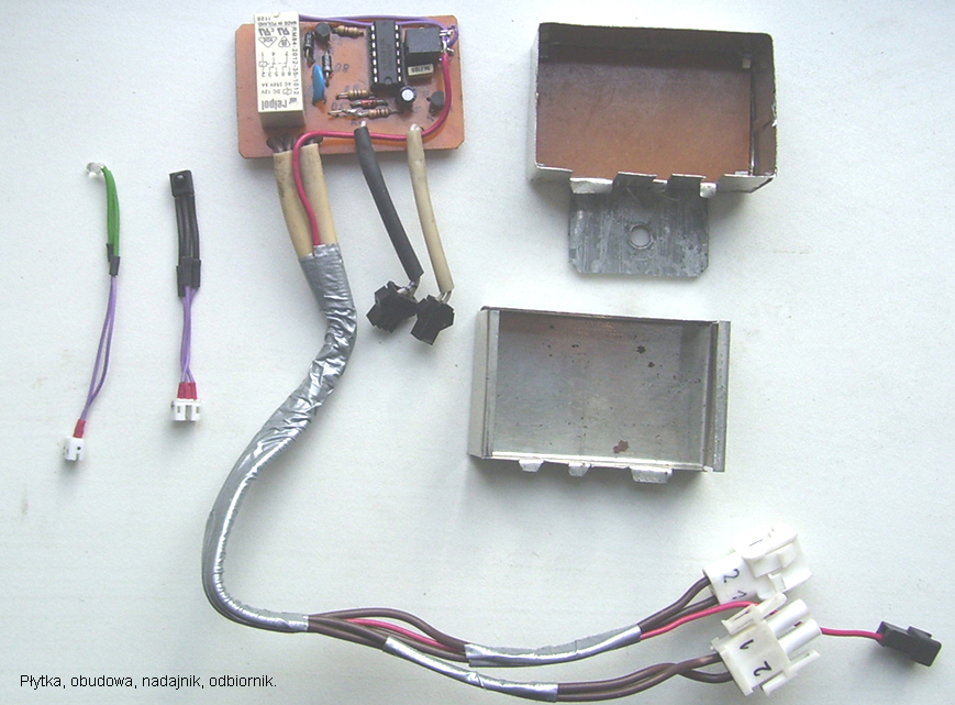
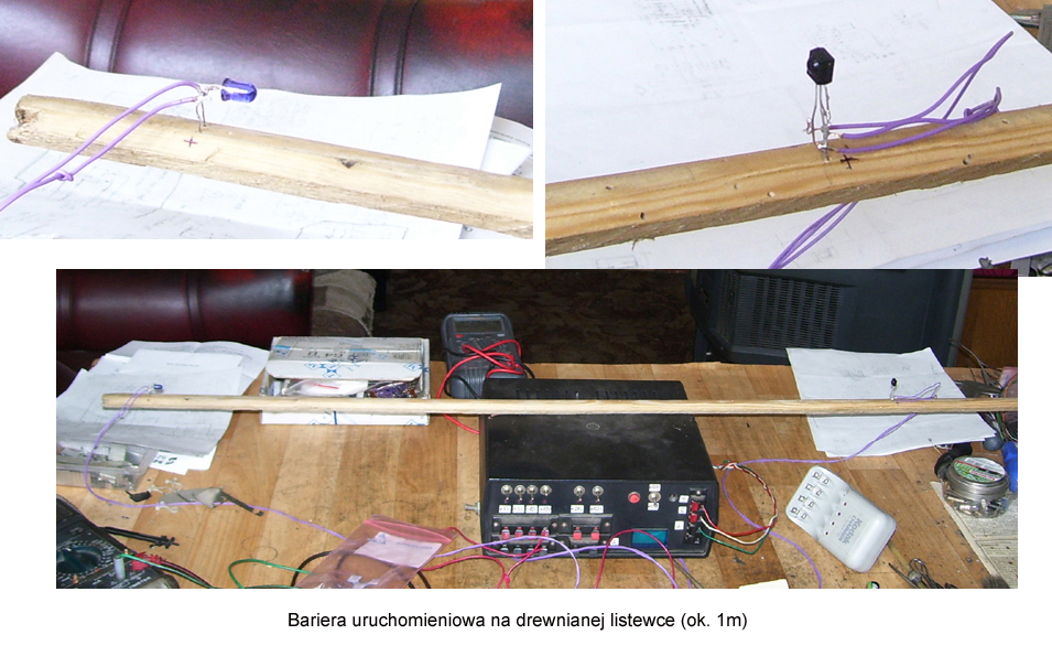
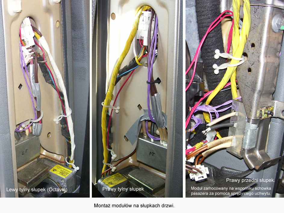
All modules: barrier, transmitting diode and receiver should be mounted in every window you want to control.
The barrier can be applied to a car with direct access to cables powering motors of glass elevators or where motors control is made directly by buttons.
Unfortunately, this device can not be so easily applied to newer cars, where motors are integrated with their drivers and there is no direct access to their power supply. In such cars you have to change connection of the contacts of the relay – the executive contacts of P1 relay should be redesigned in such a way that turning off and switching the direction of motor rotation takes place at the controls and additional power supply has to be provided to the module.

How it works:
General principle of operation is really simple. When the CLOSE button is pressed and the barrier is interrupted, motor changes the direction of rotations via relay P1 and the window goes dows instead of going up.
- barrier does not work when a window is going down using the OPEN button. The supply voltage is then cut off by diode D6
- system in sleep mode does not consume current
- when the barrier is not interrupted, closing the window is made in ordinary way
- when the CLOSE button is pressed and held and the barrier is shortly interrupted (waving hand), the window goes up, in the moment of interruption it goes down about 15cm (time constant C4, R6 is approximately 0,5s), and then will be going up until completely closes
- when the button is pressed and held and the barrier is interrupted for a longer time, the window goes up and in the moment of interruption it starts going down for as long as the interrupted barrier lasts plus additionally 15cm, then starts going up until it completely closes
- barrier permanently interrupted, such as tilting the head toward the window – even a short pressing the CLOSE button causes complete opening of the window. Interrupted barrier causes that all the time the CLOSE button is maintained by the contact 1p2 of the relay P2
- short interruption of barrier during short pressing the CLOSE button – the window goes down for 15cm, although the button is no longer pressed and the barrier is no longer interrupted (time constant C4, R6 and kept by the relay P2)
IR receiver used was chip TSOP4840 because of its small dimensions and developed gain automatics. It is insensitive to direct sunlight, even when there is no outer housing. When illuminated by an IR non-modulated carrier wave of frequency of 40kHz, the output logic state (0V) is low. When not illuminated by carrier wave of frequency of 40kHz (interrupted barrier), the output state is high (+5V). When carrier wave (40kHz) modulated, at the output there is a sine wave with an amplitude of 5V.
IR transmitter is diode D7 with a diameter of 3mm and 30 degrees angle of radiation. Large angle of radiation releases from the necessity of precise adjustment of transmitter diode and provides operation of the barrier after each removal and remounting the sensor without having to reset. When installing, just face the transmitter and receiver in a reasonable way.
Pressing the CLOSE button causes turning on the winding of the relay Z (in window control module) and contact „z” of that relay gives the supply +12V via pin 2 of the contact Z4Gx to the board of the barrier. Minus of the barrier supply is connected via pin 1 of the contact Z4Gx and normally closed in that time contact „o” of the relay O, to the ground.
Simultaneously from pins 1 and 2 of the contact Z4, via normally closed contacts 1p1 and 2p1 of the relay P1, and contact Z3Gx, the supply is given to the motor.
Generator based on gate B1 produces the course of about 500Hz frequency and that course using diode D1 chases the work of 40kHz generator on gate B2. As a result, there is a carrier frequency 40kHz modulated by frequency 500Hz in the form of packets of pulses and further, the modulated signal after amplification by transistor T1 is through transmitting diode D7 sent to the receiver US2 (TSOP4840). That happens at the gate G3 output.
At the output of 1 US2 (TSOP4840) a sine wave with a frequency of 500Hz will appear. Tension of that frequency after resistor R5 is shorted to the ground by quite large capacitance of capacitor C3, low states are at the 11 input of gate B4 and at the output 8 of gate B5. Transistor T2 does not conduct, relays P1 and P2 do not switch their contacts and the window goes up in a normal way.
In the moment of interruption of the optical barrier, there is high state (+5V) at the output 1 TSOP4840, at the input 11 of gate B4, at the output 8 of gate B5. Transistor T2 conducts, relay P1 changes the direction of motor rotations by contacts 1p1 and 2p1. Relay P2 maintains the button on by contact 1p2. The time of maintaining depends on the time constant of the elements C4, R6.
Diode D3 does not allow the capacitor C4 to quickly discharge, when the barrier is no longer interrupted (low state on C3).
Resistor R5 and total capacity of capacitors C3 and C4 provide a slight delay in the appearance of high state at the 11 input of the gate B4. The delay prevents from „slapping” of the relay P1, and therefore shaking the motor at the moment of turning on the power supply, before the work of generators and receiver TSOP4840 stabilizes.
Varistor R9 prevents from sparking the relay P1 contacts. Diode D2 accelerates the discharge of the capacitor C3 after the disappearance of high state at the output 1 TSOP4840.
There is no 5V IC stabilizer, because the stabilization by means of Zener diode is sufficient. Resistor R8 serves as protection against all types of short circuits in the wires oto the receiver TSOP4840. A similar protective role plays reducing resistor R4. Those cables are relatively thin and long, and they are easy to wipe and short circuit.
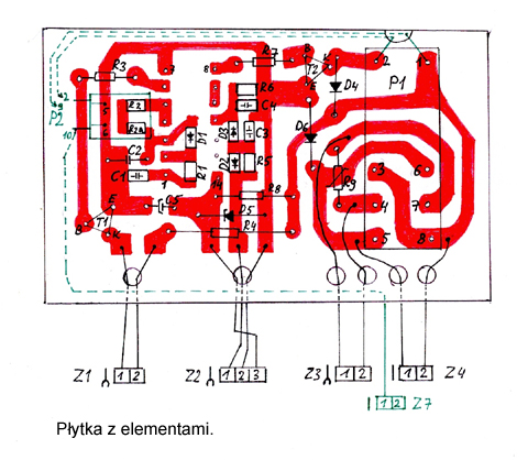
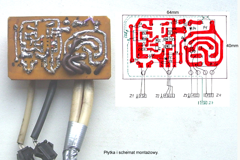
Relay P2 is marked green on the scheme, because it was mounted later as an improvement of the system. That is why the PCB does not contain a „print” for it. It was soldered by side, two pins 5 and 6 into the path of ground and the remaining pins were connected by cables. In addition, it was glued by a double-sided adhesive. Relay P2 has very small dimensions (12x9x7mm), so it can be mounted in any place of the board.
Relay P2 prevents from immediately stop the window at the moment you release the button when the barrier is interrupted.

Link to original thread (useful attachment) – Bariera optyczna w samochodzie