lxmn
Newbie level 6
- Joined
- Apr 2, 2012
- Messages
- 12
- Helped
- 0
- Reputation
- 0
- Reaction score
- 0
- Trophy points
- 1,281
- Location
- The Green Planet
- Activity points
- 1,386
Hi Everybody,
I am currently trying to build a 500W, 100kHz buck boost converter, with Vin = 25to 35 Vout = 25 / 50 V. Switch MOSFET : IRF 3710
I am a bit confused about a number of things.
1. Should i be using a high side + low side driver like IR 2110 or a optocoupler based TLP 250 would suffice?
i feel ir 2110 is redundant since i need to drive only one mosfet. But i have heard TLP works satisfactorily only upto 25 kHz or so (?????).
2. Do i need to use a bootstrap circuit at all or is it required since the output / source is not at ground zero potential ( i am clearly a bit confused about when and where the bootstrap circuit is needed )
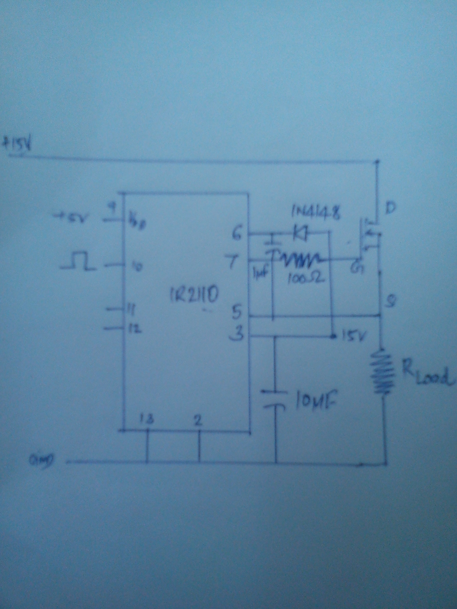
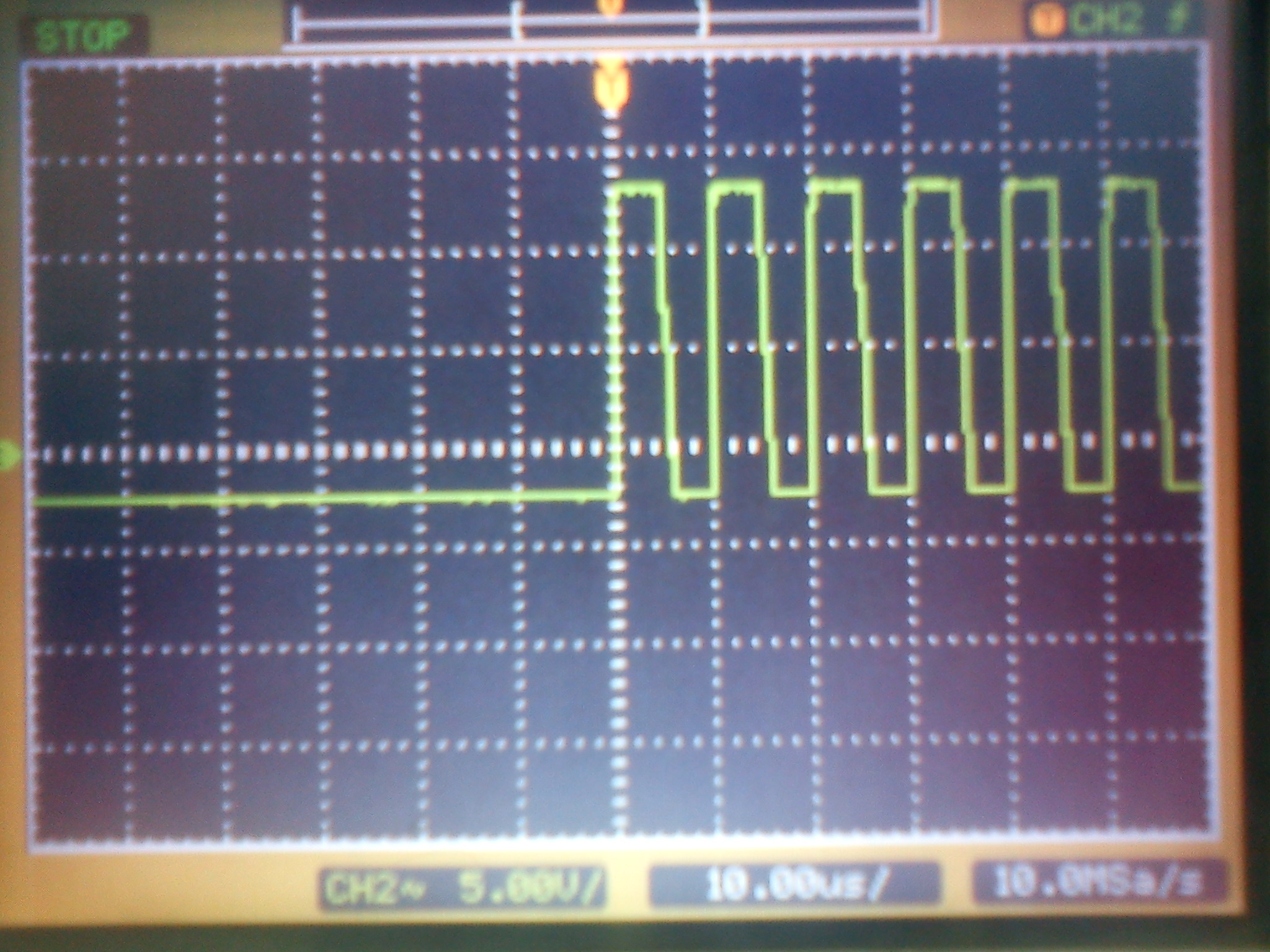
3. I have tried using ir 2110 , following the design equations given in the application note ( C> .1 uF) , i had used bootstrap capacitor ( electrolytic) C = 1uF , lower C = uF and bootstrap diode 1N4148. The resistor in series with the gate was 100 ohm ( random selection ). But with these values the test circuit didnt workout . I would like to know , on what basis do we fix the values of the R and the lower C?
Thanks in advance.....")
I am currently trying to build a 500W, 100kHz buck boost converter, with Vin = 25to 35 Vout = 25 / 50 V. Switch MOSFET : IRF 3710
I am a bit confused about a number of things.
1. Should i be using a high side + low side driver like IR 2110 or a optocoupler based TLP 250 would suffice?
i feel ir 2110 is redundant since i need to drive only one mosfet. But i have heard TLP works satisfactorily only upto 25 kHz or so (?????).
2. Do i need to use a bootstrap circuit at all or is it required since the output / source is not at ground zero potential ( i am clearly a bit confused about when and where the bootstrap circuit is needed )
3. I have tried using ir 2110 , following the design equations given in the application note ( C> .1 uF) , i had used bootstrap capacitor ( electrolytic) C = 1uF , lower C = uF and bootstrap diode 1N4148. The resistor in series with the gate was 100 ohm ( random selection ). But with these values the test circuit didnt workout . I would like to know , on what basis do we fix the values of the R and the lower C?
Thanks in advance.....