harinisas
Newbie level 6
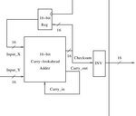
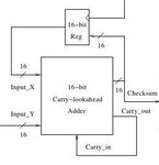
hi i am writing a code for a circuit where the input to the 16 bit carry look ahead adder is output of the d flipflop and input to the flipflop is output of the adder its like a loop when i am writing the code i am unable to see the output so please help me its urgent i want the code in verilog.
Attachments

Last edited: