Continue to Site

Welcome to EDAboard.com

Welcome to our site! EDAboard.com is an international Electronics Discussion Forum focused on EDA software, circuits, schematics, books, theory, papers, asic, pld, 8051, DSP, Network, RF, Analog Design, PCB, Service Manuals... and a whole lot more! To participate you need to register. Registration is free. Click here to register now.

AC voltage sensing without transformer and POTentiometer

Status
Not open for further replies.

mohansaini

Junior Member level 1
Joined
May 22, 2010
Messages
18
Helped
1
Reputation
2
Reaction score
1
Trophy points
1,283
Location
india
Activity points
1,414
Please suggest how to sense AC voltage without isolation transformer by using combination of Resistance and Capacitors. i need to convert AC 230V to a level of 0-5V so that i can sense it using a Microcontroller. I have heard about isolated OP-AMPS are used for that purpose but never used them practically please share your ideas and circuits or work whatever you have done before the same.


Thanks.
 

The resistor / capacitor circuits are simply voltage dividing ; and can only be use (with a lot of care as there is no isolation) for low load current applications.
Isolated opamps are used for signal only (no power transfer) and use magnetic or optical isolation techniques
 

There is no issue related to current as my main motive is to display that voltage at LCD or Seven segment but its all about signal conditioning and parameters which has to be considered during design of such circuits.Can you please provide any example related to magnetic/Optical isolation for such kind of designing.
 

Please give more detail on the parameters of the AC voltage that you want to measure
 

This assumes you don't mind having your device exposed to mains voltage.

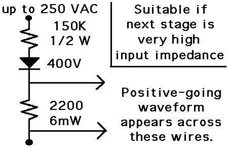
If your measuring device has a high input impedance (say 50k) then you can use low-power resistors to divide down 230 VAC.

Say, as in this layout:

78_1332929169.gif


Suppose you must accommodate a max of 350V (peak level of a 250 VAC sine).
Resistor values were chosen to bring it down to 5V or so.

The diode is included in case you only want to measure the positive-going waveform.

It may instead be necessary to put a diode at the input to your measuring device. The diode drop will throw off the linearity of your measurements. You'll need to calibrate to a meter or other trustworthy method.
 
Last edited:

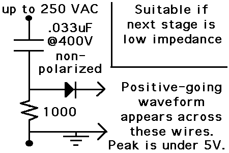
This schematic uses capacitive drop. It can work when the next stage has a lower impedance. From, say, 1k and up.

Anyway it works in a simulation.

The diode cannot be inline with the capacitor when the wire is carrying AC.

The diode must be rated for 400 V reverse. It could be lethal for your measuring device if there is any current flow up from the ground, backwards out the input.

As stated already, this method is is a HIGH VOLTAGE risk.

89_1332962270.gif
 
Last edited:

Thanks for your reply.
@Klystron i need to make a Phase selector which will sense 3-phase input supply and will select the healthy phase to drive the load.
I want to sense this voltage without any transformer and POT. I am using PIC18F452 Micro controller for that purpose driving load is a decision making part which is separate from sensing for that purpose i am using a contactor combination.
But my first requirement is to sense that I/P AC voltage properly.
 

i need to make a Phase selector which will sense 3-phase input supply and will select the healthy phase to drive the load.

It will reduce risk to your PIC if you use an optocoupler between it and the house AC.

The led inside the optocoupler can be driven by the circuit at this link. It uses capacitive reactance to reduce the AC volt level.

https://www.electronicsarea.com/Light-emitting_diode_connected_120-240VAC.asp

If by healthy you mean the strongest amplitude then you are probably talking about using 3 detectors to monitor the 3 supply wires independently.
 

Exactly i am talking about the strongest amplitude.. but as per my thinking an optocoupler can work as 0 and 1 only, i can not get a variable i/p at ADC of my PIC.
 

If You want optical isolation You have to build an lineair opto-amplifier.
You will find some examples here.
(or You gonna end up with exotic parts which do exactly the same)
Here You can find some information on how to do it.
**broken link removed**

Good luck and be carefull.
 

Exactly i am talking about the strongest amplitude.. but as per my thinking an optocoupler can work as 0 and 1 only, i can not get a variable i/p at ADC of my PIC.

It's possible optocouplers behave differently in this regard.

It's true that an led can light with only a few uA going through it.

I forget how it happened in experiments with my collection of old opto units, whether by limiting current through the internal led to, say, a milliamp maximum, that it would vary the brightness on the internal photodetector, thus yielding a range of response between full on and full off.

It may be worth a try, to put from 1 to 10 megohms in series with the opto led.
 

Status
Not open for further replies.

Similar threads

Part and Inventory Search

Welcome to EDABoard.com

Sponsor

Back
Top