Continue to Site

Welcome to EDAboard.com

Welcome to our site! EDAboard.com is an international Electronics Discussion Forum focused on EDA software, circuits, schematics, books, theory, papers, asic, pld, 8051, DSP, Network, RF, Analog Design, PCB, Service Manuals... and a whole lot more! To participate you need to register. Registration is free. Click here to register now.

current transformer waveform

Status
Not open for further replies.

neonwarrior

Member level 2
Joined
Dec 23, 2010
Messages
47
Helped
4
Reputation
8
Reaction score
4
Trophy points
1,288
Activity points
1,610
Hello everyone
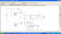
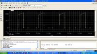
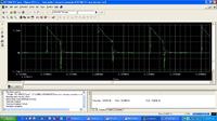
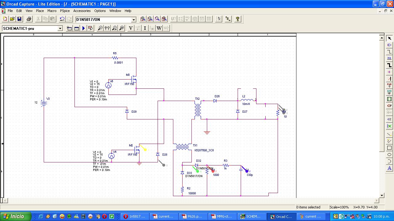
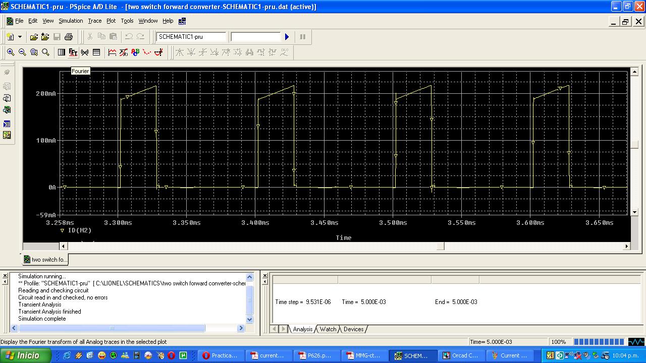
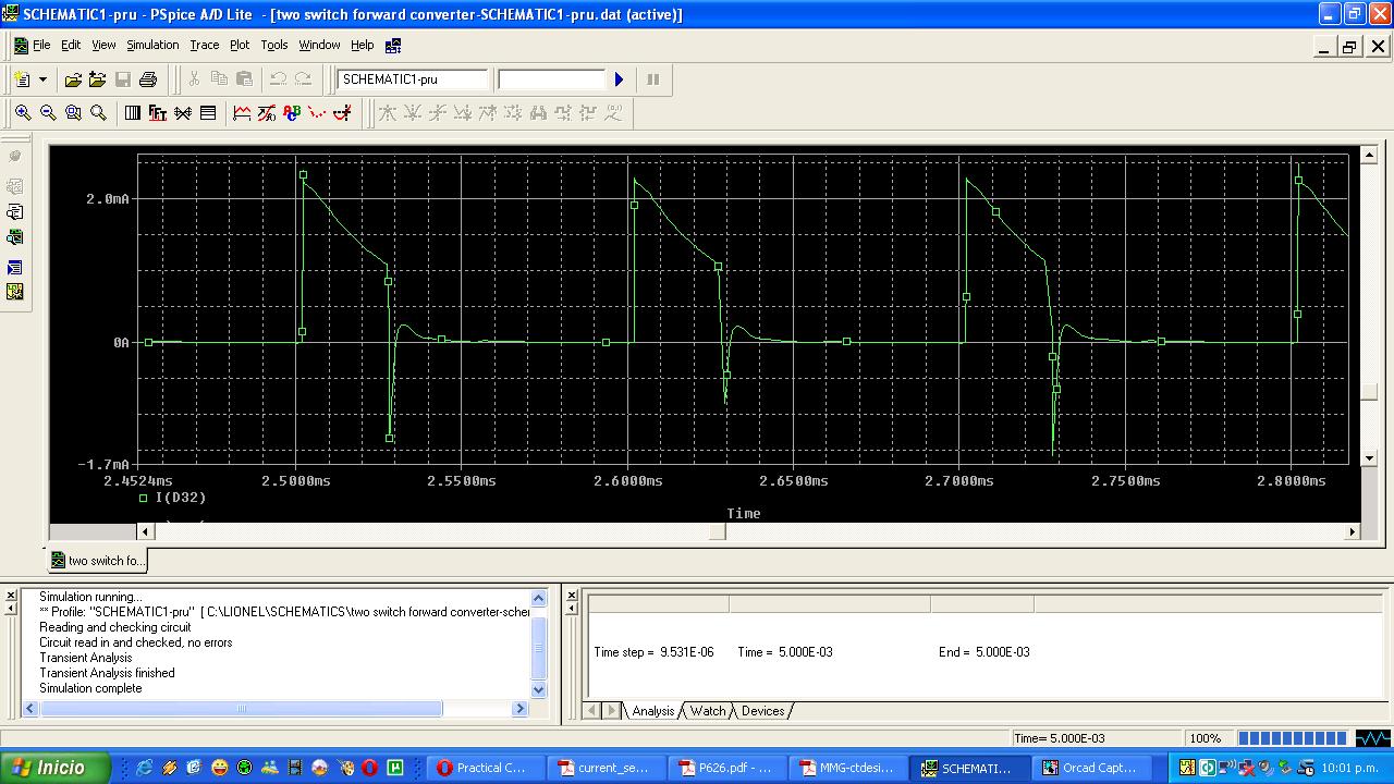
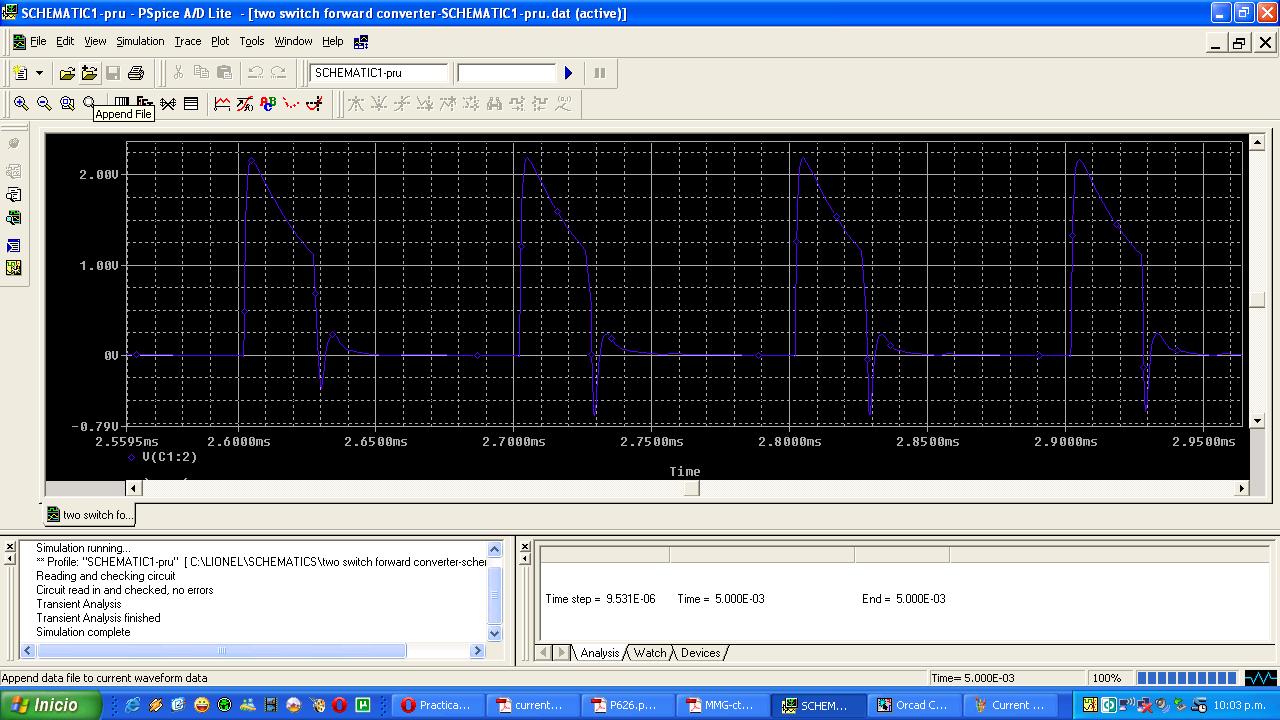
I'm simulating a two switch forward converter with a current sense transformer on the primary side. I saw that the current sense transformer primary current increases linearly. But the current sense transformer secondary current and voltage decrease linearly.
Is this ok or the current on the secondary of current transformer must increase too??
Here the waveforms...


Thanks in advance.
 

You don't show any transformer parameters except for a core model, so there's no exact answer to your question so far.

Generally, the transformer main inductance forms a high pass time constant with the load resistor (T = L/R) which apparently shows in the waveform.
 
The CT output should have the same shape as the primary current, so something's wrong. But without knowing any electrical parameters of your transformers it's hard to tell what. I would assume, like FvM implies, that your burden resistor is to high compared to the CT's magnetizing inductance. Try decreasing the burden resistor to 100 ohms or so and see if that helps.
 
CT must have small resitor direct connect CT secondary. Diodes for dv voltage converstion must be connected "after" this resistor. In schematic there are different resistor values for each diode.
 

The used diode configuration has been suggested in a Pulse datasheet (see https://www.edaboard.com/threads/245693/#post1051295), but I won't use it due to it's current dependent time constant. Placing the diode after the shunt resistor brings up other problems. If you want low high-pass cut-of frequency and linear response, you should better refer to an active circuit utilizing an amplifier.
 

Having a diode before the burden resistor should not be a problem. Yes it means that the system won't have a well defined lower cutoff frequency (or time constant), but generally that cutoff will always be well below your bandwidth of interest, so it shouldn't have a noticeable impact on performance.

When using a diode before the burden, it is wise to provide a current path in the reverse direction, which can be done with a reverse clamping diode directly on the CT output.
 

"Orcad Capture" let you change only coupling N1 and N2 turns for the transformer.
I drecrease the burden resistor to 10 ohm as suggested and problem solved. Now the current is proportional to transistor current.
Do you know another circuit simulation program that let you change transformer parameters???
Thanks
 

"Orcad Capture" let you change only coupling N1 and N2 turns for the transformer.
I wonder, which transformer parameters you are missing?

PSpice ("Orcad") can either use a linear or non-linear transformer model. According to your schematic, you're using the non-linear (core) model. By changing the core parameters, you can basically model any kind of transformer.

The linear model uses inductance and coupling parameters and is more simple to use, if you know the transformer specification and don't need to consider core saturation, losses or non-linear inductance.

Everything is explained in the PSpice Refernce Guide.
 

PSpice ("Orcad") can either use a linear or non-linear transformer model. According to your schematic, you're using the non-linear (core) model. By changing the core parameters, you can basically model any kind of transformer.

How I can change the core parameters? I read in the pspice reference guide as you suggested that there are many parameters I can change but I don't know how
Model parameters* Description Units Default
A Thermal energy parameter amp/meter 1E+3
AREA Mean magnetic cross-section cm2 0.1
C Domain flexing parameter 0.2
GAP Effective air-gap length cm 0
K Domain anisotropy parameter amp/meter 500
LEVEL Model index 2
MS Magnetization saturation amp/meter 1E+6
PACK Pack** (stacking) factor 1.0
PATH Mean magnetic path length cm 1.

Thanks in advance.
 

You can either write your own model or change individual parameters in the model instantiation. But you didn't tell yet, what you want to achieve.
 

Status
Not open for further replies.

Similar threads

Part and Inventory Search

Welcome to EDABoard.com

Sponsor

Back
Top