Vermes
Advanced Member level 4
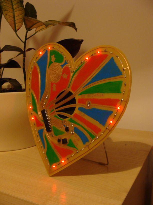
Described here Valentine's Day gift is in the form of a heart with diodes blinking around and a speaker inside playing a song. The heart was made of laminate, and the paths were designed so that they provide graphic form. Paths were painted with an oil pen.
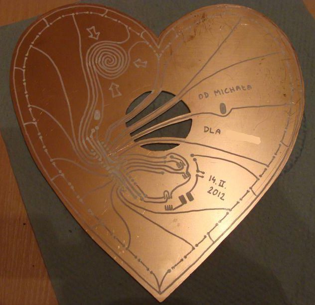
Please do not copy that picture for laminate, because there are some mistakes on it. You better use the scheme below:
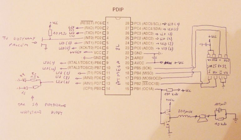
Tha main element of the device is well-known microcontroller Atmega 8L, which plays the sound stored in the external Flash memory. Internal PWM of Atmega is used for playing. The PWM operates with a frequency of 32 kHz and 8bit resolution (although the sound is stored in the memory with sampling frequency 16kHz). Signal form the PWM controls the key on two MOS transistors (in this case, it is one double transistor N-P Si4532DY), which directly powers a 32-ohm speaker. A 220 uH coil, which suppresses the carrier 32 kHz was connected in series with the speaker in order to reduce the current consumption. The sound quality can be compared to a kitchen radio (small speaker), without noise and crackles. Due to quite big size of the board (cut of A4 laminate), the heart plays role of a baffle of the speaker, so lower frequencies are better heard.
4-megabyte memory is SPI Flash M25PX32 (TME), which can store more than 4 minutes of a record. In interruptions between reads of the memory, the processor switches on and off the LEDs located on the perimeter of the heart.
The system has no power switch. DC voltage from NiMH accumulator 3,6V/600mAh supplies the processor and other elements, but normally both processor and the memory are in sleep. The song is triggered by touching the „snail” - touch switch, whose task is to wake up the processor by generating an interrupt on pin INT0. After the play is finished, the processor puts the memory to sleep and then goes into Power Down mode. Total current consumption in sleep state is 7uA, and while playing – about 25mA.
SPI cables were soldered directly to the processor's legs on order to program. Flash memory programming with a record can be made through a serial port, using a script written in Matlab.
You will need MAX232 or FTDI to connect Atmega with a computer. In addition to the RX and TX pins, also DTR pin is supported – connected to the RESET input in Atmega. With this, the script can put the controller into data charge mode.
The charge script carries out data transfer and slight compression of the song dynamic, so as to increase the volume a little.
Here is the picture of the device after soldering the elements, before painting.
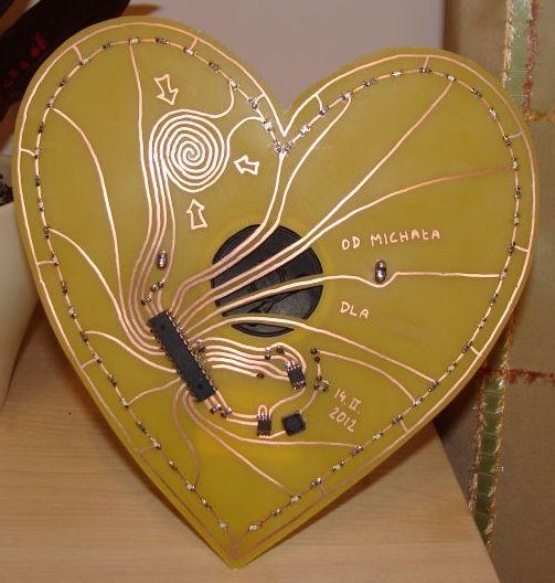
Due to the thickness of painted paths, processor in DIP housing was selected, but it has cut pins and is soldered by the surface. All the other elements (except the socket for the battery and electrolytic capacitor in the speaker's housing) are in SMD housings.
Link to original thread (useful attachment) – Walentynka-pozytywka
")