Continue to Site

Welcome to EDAboard.com

Welcome to our site! EDAboard.com is an international Electronics Discussion Forum focused on EDA software, circuits, schematics, books, theory, papers, asic, pld, 8051, DSP, Network, RF, Analog Design, PCB, Service Manuals... and a whole lot more! To participate you need to register. Registration is free. Click here to register now.

voltage sensing circuit

Status
Not open for further replies.

power--man

Junior Member level 1
Joined
Mar 20, 2012
Messages
18
Helped
1
Reputation
2
Reaction score
1
Trophy points
1,283
Activity points
1,405
hi there guys

will the circuit below work?

untitledq.JPG

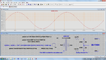
A 1k ohm load is connected to mains and a step down transformer( 230V to 12V) connected across the load. i want to sense the voltage of the load. The voltage at the secondary side is then brought down further with the use of resistors to a appropriate value of 660mv to be fed into the mcp3909. I require a plus and minus AC voltage at the output to be fed into the mcp3909
 

Welll, first of all, you are going to need a 53 Watt resistor there; that'll get warm!.

Your output voltage is going to be 0.75 V (not sure how you got 660mV). And that .75V is RMS, which means you've got a little more than 1 volt PEAK, which exceeds the range of the MCP3909(+/- 1) by a little bit ; you probably want to have a little headroom.
 

thanks for the reply guys

the 1k resistor is an example, inplace of the the 1k resistor im goin to hav a appliance for example a kettle, only for simulation purposes i used a 1k resistor. im designing a circuit that senses voltage of an appliances and then sends the reading to the mcp3909. the mcp requires a AC input.

any advice if im goin about it the right way
thanks
 

The point is that the differential output is within 660mV for good linearity (mcp3909).

First, we assume the worst case of the highest mains voltage is 240Vrms
This gives an RMS voltage at the transformer secondary:
Vs_rms = 12/220 * 240
Its peak voltage:
Vs_peak = 12/220 * 240 * SQRT(2) = 12/220 * 240 * 1.414
Its peak to peak voltage:
Vs_pp = 12/220 * 240 * 1.414 * 2
Vs_pp = 37 V

We will remove R5 and R6
R2 will be splitted as R2 and R3 in series. Their mid-joint will be connected to Agnd of mcp3909.
We let the values of R2 and R3 be equal and relatively low (in comparison to the input impedance of 390K, datasheet):
R2 = R3 = 470R
R1 and R2 will form a voltage divider for CH1+ (or CH1-).
And we add R4 so that R4 and R3 will form a similar voltage divider for CH1- (or CH1+).
R1 = R4 = (37-0.660) / 0.660 * 470 = 25878 => 27K

Therefore:
@240Vrms input, the upper voltage divider (R1 & R2) gives a peak voltage:
V_up = 240 * 12/220 * 1.414 * 0.47 / (27 + 0.47) = 317mV
@240Vrms input, the lower voltage divider (R4 & R3) gives the same peak voltage but opposite:
V_lw = 240 * 12/220 * 1.414 * 0.47 / (27 + 0.47) = 317mV

V_differential = 2* V_up = 317 * 2 = 634 mV which is close to 660mV

Of course you can lower R1 & R2 to be 22K if the mains voltage won't go high.
In this case @220Vrms input:
V_differential = 2* V_up = 2 * 12 * 1.414 * 0.47 / (22 + 0.47) = 710 mV a bit higher than 660mV

This was one possible solution.

Kerim

PS: Please see correction below
 
Last edited:

Other than changing your divider ratio, it looks ok. Just be careful of that 230 V
 

You are right, and I think I was confused about the peak to peak voltage... Only the peak value should be used. I will try to correct the values. For instance, my mains voltage could go up to 245V if not 250V so I was generous by assuming it 240V :)

=================

Correction:

The point is that the differential output is within 660 mV for good linearity (mcp3909).

First, we assume the worst case of the highest mains voltage is 230 Vrms
This gives an RMS voltage at the transformer secondary:
Vs_rms = 12/220 * 230
Its peak voltage:
Vs_peak = 12/220 * 230 * SQRT(2) = 12/220 * 230 * 1.414 = 17.75 V

We will remove R5 and R6
R2 will be splitted as R2 and R3 in series. Their mid-joint will be connected to Agnd of mcp3909.
We let the values of R2 and R3 be equal and relatively low (in comparison to the input impedance of 390K, datasheet):
R2 = R3 = 470R
R1 and R2 will form a voltage divider for CH1+ (or CH1-).
And we add R4 so that R4 and R3 will form a similar voltage divider for CH1- (or CH1+).
R1 = R4 = (17.75-0.660) / 0.660 * 470 = 12170 => 12K
 
Last edited:

Thank you kerimF, i hav a fair idea as to how the circuit is goin to look but im not 100% certain, could you please post up a picture as to how the circuit will look, it will be much appreciated

thanks again
 

Kerim, I think you've got it a bit wrong. First, it was stated that the transformer was 230 in/12 out; for some reason you are using 12/220. It's not immediately clear if the input to the MCP3909 can accept a floating input (the maximum common-mode voltage is +/- 1V). What I would do is put a voltage divider on each leg of the transformer, and drive the inputs from that. Assuming the maximum input voltage is 240 volts:

240*12/230*1.414*R2/(R1+R2)=0.66V

(R1=390)=> R2=14 ohms.
 

Thank you barry... It seems I am getting old rather quickly :)
 

Attachments

  • Vsence_02.pdf
    6.7 KB · Views: 89
Last edited:

Sorry Kerim, still wrong. Your schematic will work, but it's .668V peak, not peak-to-peak. (A 12V RMS signal is 12*2*1.414 V p-p). And I still don't know why you are using 220 instead of 230.
 

Because I uploaded version 01 before reading your post ;)

So I corrected it in version 02 :)

Note: This is my problem in designing since 35 years ago... I do a lot of silly mistakes before every new board competes other similar products in the market (at least in the local one ;-) ).
 
Last edited:

Thank you so much guys

so all i have to do now is connect an appliance to mains and using this circuit it would sense the voltage and send it to the mcp3909?
 

I guess. Just be careful! 230 will kill you. Have somebody you don't like test it for you.
 

lol barry!!... thank you both guys alot, apologise 4 late reply was not at college, i tried simulating it now but when i set my turns ratio of the transformer to (Vs/Vp)....12/230= 0.05, i get 89V at output ch1 and ch2, am i doin sumting wrong? and kerim what did u mean by post7 when you said "the input impedance of 390K, datasheet" ?

thanks guys

---------- Post added at 12:57 ---------- Previous post was at 12:48 ----------

when i set my primary to secondary windings to 7 on the transformer for simulation, then i get 646mV at ch1 and ch2, but why 7?
 

Please refer to the two attached pics.
 

Attachments

  • Vsence_03.png
    Vsence_03.png
    108 KB · Views: 70
  • MCP3909.png
    MCP3909.png
    62.4 KB · Views: 85

THank you kerim for all your help
 
  • Like
Reactions: KerimF

    KerimF

    Points: 2
    Helpful Answer Positive Rating
hi guys hope yorl are well, how do i get analogue ground ? if im using a breadboard to get the +-660mv with no load connected
 

Just measure the voltage on the two resistors (470R + 470R) while ignoring their mid-connection.

Please note, in a real circuit that uses a transformer, there is no need to have on its both sides the same ground (a node assumed having voltage 0 relative to all others).
Therefore, in your circuit, for test or the working one, forget about the ground shown on the left side of the simulated circuit (post #17).

Also the test doesn't need the ground on the right side too if you like just checking the +/- 660 mV.

But for the final circuit, the ground on the right side should be connected to the analogue ground pin of the IC to avoid the interference which could come from the fast or strong digital signals. This is why there is a return pin (also ground pin) for the digital currents. But if you measure by an ohmmeter the resistance between the analogue and digital ground pins, you will find it very close to zero (like a real short). The idea behind having two grounds is just to separate (outside and inside the IC) the paths of the weak analogue currents from the fast strong digital ones. This reduces to a great extent possible induced interference which could generate parasitic currents and/or voltages on the analog side (sometimes low level digital signals could be affected by the high level ones if they share the same ground track). You will likely learn this subject gradually with time when necessary.
 

Status
Not open for further replies.

Part and Inventory Search

Welcome to EDABoard.com

Sponsor

Back
Top