Continue to Site
Follow along with the video below to see how to install our site as a web app on your home screen.
Note: This feature may not be available in some browsers.
If only the following data are known in a negative feedback system is it possible to make a conclusion about stability or not?
That was my feeling as well (not enough information), although this came up in a interview question of one of my friends recently. He had only 2 choices of answers. Is this system stable or not.
Perhaps the interviewer did want exactly this as an answer - namely that additional information is needed.
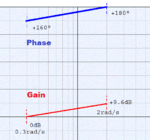
The expected answer is NO, since the gain is greater then 0 dB for a phase shift of 180°
This assumes that there is another another 180 degree phase shift in the feedback due to an inverting error amp or something. But since that's not given in the problem, then this isn't necessarily true.The system has only 20° of phase margin at 0dB gain and has no gain margin (gain is +9.6dB) at 180° phase so it would seem that the system is unstable and the answer is b- No.
The original post says "in a negative feedback system"This assumes that there is another another 180 degree phase shift in the feedback due to an inverting error amp or something.
If we see the question and image as it says, this is the correct answer.The system has only 20° of phase margin at 0dB gain and has no gain margin (gain is +9.6dB) at 180° phase so it would seem that the system is unstable and the answer is b- No.
If we see the question and image as it says, this is the correct answer.
Yes, but that doesn't mean the amp is or isn't actually included in that plot. Often when looking a bode plots of closed loops, you actually include the entire loop, including the error amp, and thus you look for crossings of 360 degrees, not 180.The original post says "in a negative feedback system"
Yes, I agree that you cannot say if the system is stable unless you have full information. But you can say that it is not stable from this bit of info - I cannot point to the theory, but it looks clear to me.And FwM/LvW also bring up to valid point that bode plots often aren't sufficient for actually determining stability. Especially in the case where there are multiple crossings of 180/360 degrees of phase. A nyquist plot is necessary for that.
The loop has a positive gain of 3 at 0.3Hz: I cannot imagine a linear system being stable given this premiss, whatever the loop gain may be outside the given frequency range.