Vermes
Advanced Member level 4
This device was designed for educational purposes. It allows wireless transmission of information using a laser beam of wavelength 650 nm and output power of less than 5mW as a transmission medium. Microcontroller software PIC16F84A filters data packages sent by the communication program running under Microsoft Windows. The data transmission between DCE and DTE is performed according to standard RS232.
Method of transmission of information is presented in the form of block diagram. The transmission takes place through the free space by a beam of light. It required the construction of an optical communication system.
Basic devices included in the system:
- source of information
- transmitting encoder
- optical transmitter
- optical detector
- receiver decoder
- recipient of the information
Communication between the source of information and transceiver that includes the modules: transmitting encoder, optical transmitter, receiver decoder, optical detector is a standard RS232. Transceivers can be connected in pairs, or create a network which includes many devices connected to each other according to the topology of the ring. Data are transferred between them via the FSO link.
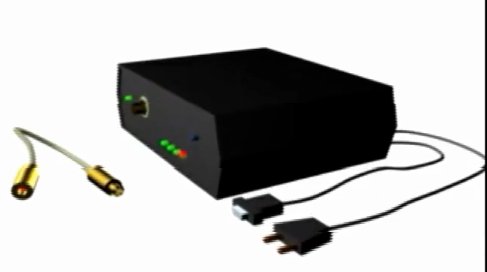
The device has module construction. Transmitting and receiving modulse should be connected to the main board, on which there is microcontroller PIC16F84A and MAX232 responsible for the communication with the computer.
Transmitter module:
Main board:
Receiver module:
Software for the transmission of data by optical link was designed for Microsoft Windows and as a built-in system for microcontroller PIC16F84. Tasks were divided in three layers, implemented by separate applications and circuits:
- microcontroller's program – control over the data flow, capsulation and encapsulation of the packages
- driver – DDL library run on a PC allows to communicate between the microcontroller and the application
- application – program run on a PC is equipped with a form allowing a dialogue with the user
Link speed is limited by the capacity of the COM port. Stable link was got between the stations distant from each other <10m. The solution of mounting the laser diode on a flexible wire allows easy targeting the diode in the desired direction, but is very unstable. Even the people passing cause shocks of the floor and slight movements (roll) of the diode and the receiver at a distance of more than 5m may stop to be illuminated by the laser beam.
Application run on a PC:
Inside the housing:

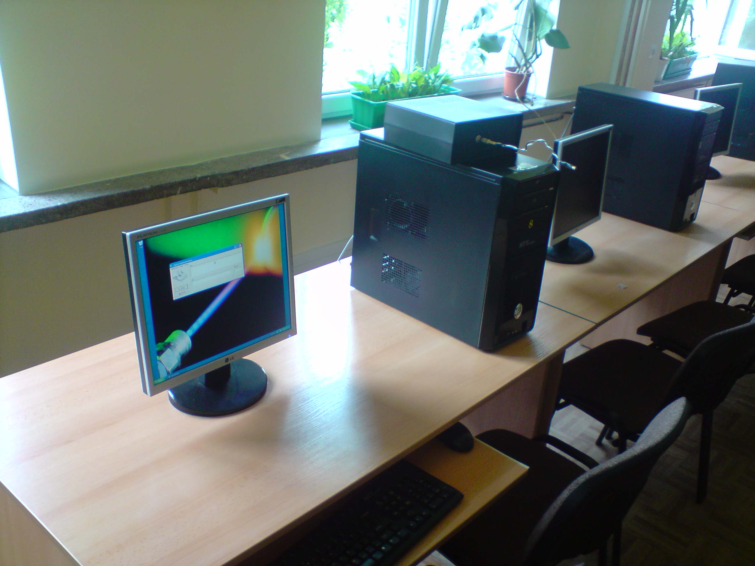
One of the workstations. The transceiver device can be seen on the computer:
Link to original thread (useful attachment) – FSO Sieć z laserowym łączem wolnej przestrzeni