DLam
Newbie level 4
Hi there,
I hope I'm posting to the right forum about this. I am building a DIY brushless 3-phase speed controlled for my RC plane. To do so, I have constructed a circuit involving 6 pairs of RFP30N06 MOSFETs arranged in totem-pole fashion – each pair being driven by a TC427 dual MOSFET driver – and an ATMEGA 1080 to control the pulses. When hooked up to a Neodym 300 1400kV 93W motor with an 8x6 prop and an E-flite 2S 25C 800mAh lipo to the circuit, it drives the motor quite well at lower speeds (e.g. 1000 rpm). However, at around 5000rpm, the motor stops spinning and emits a high-pitched whine. After some investigation, i figured out that the motor was not receiving enough current ([~8 amps]*7.4V = 59.2W: no where close to 93W). I chose the RFP30N06 specifically for its low threshold voltage (3V -> 20A). This is where I have a question.
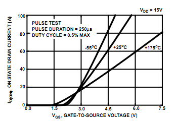
The MOSFETS are turned on for 1/3 of each cycle. The full cycle at 5000rpm is approx. 1ms long. The voltage for each pulse is at 7.4 volts. Would that mean that the collector current would mimic more that for 7.4/3 [2.47V], [~5-10A max.] on the transfer characteristics graph or 7.4 volts [MOSFET is turned fully on]?
I've been at this for months, but the lack of current continues to plague me :sad:. Any help would be greatly appreciated. Thanks,
DLam
I hope I'm posting to the right forum about this. I am building a DIY brushless 3-phase speed controlled for my RC plane. To do so, I have constructed a circuit involving 6 pairs of RFP30N06 MOSFETs arranged in totem-pole fashion – each pair being driven by a TC427 dual MOSFET driver – and an ATMEGA 1080 to control the pulses. When hooked up to a Neodym 300 1400kV 93W motor with an 8x6 prop and an E-flite 2S 25C 800mAh lipo to the circuit, it drives the motor quite well at lower speeds (e.g. 1000 rpm). However, at around 5000rpm, the motor stops spinning and emits a high-pitched whine. After some investigation, i figured out that the motor was not receiving enough current ([~8 amps]*7.4V = 59.2W: no where close to 93W). I chose the RFP30N06 specifically for its low threshold voltage (3V -> 20A). This is where I have a question.
The MOSFETS are turned on for 1/3 of each cycle. The full cycle at 5000rpm is approx. 1ms long. The voltage for each pulse is at 7.4 volts. Would that mean that the collector current would mimic more that for 7.4/3 [2.47V], [~5-10A max.] on the transfer characteristics graph or 7.4 volts [MOSFET is turned fully on]?
I've been at this for months, but the lack of current continues to plague me :sad:. Any help would be greatly appreciated. Thanks,
DLam
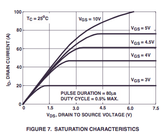
 . Could that really be an issue? I don't know whether saturation characteristics are applicable in this case, but I thought that 7.6 V for any gate voltage would be enough to saturate the FET judging by the graph: