Moha99
Junior Member level 1
Hey all!
I have a DC/DC converter that I bought a week ago.
What im doing is using it in some project, using a battery as the power supply and the converter as a step up transformer and sometimes a stop down.
Problem is when i use the converter to power a small DC motor, it works for a few seconds and just stops! and i try to connect it again dosen't work.
On the converters board there is a small red LED that indicates the power!
When i connect the battery it lights up, i connect the output with a higher voltage from 12volts/IN to 13 -16/DC volts/OUT to the motor the LED light fades away slowly and the motor stops.
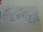
I said to myself their could be a problem with the charge or something... So I used a capacitor at 16 volt 2200 MicroFarads and a 3 AMP diode following this diagram exactly!:

So what really is the problem here? Im trying to power the DC motor using this converter all details in the link:
**broken link removed**
And the DC/Motor type and specs:
**broken link removed**
I say that there's a im not sure what they call it in the "electric world" im kinda new it :???: I think there a BACKFIRE of current maybe it flowing back to the capacitor or something?
*Note: I connected everything correctly interms of the + AND THE - terminals, I need to use the converter in this project it a MUST.
+ I used more than one type of converter with similar spec's still has the same problem. + The power supply is perfect no problems with it at all.
I have a DC/DC converter that I bought a week ago.
What im doing is using it in some project, using a battery as the power supply and the converter as a step up transformer and sometimes a stop down.
Problem is when i use the converter to power a small DC motor, it works for a few seconds and just stops! and i try to connect it again dosen't work.
On the converters board there is a small red LED that indicates the power!
When i connect the battery it lights up, i connect the output with a higher voltage from 12volts/IN to 13 -16/DC volts/OUT to the motor the LED light fades away slowly and the motor stops.
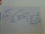
I said to myself their could be a problem with the charge or something... So I used a capacitor at 16 volt 2200 MicroFarads and a 3 AMP diode following this diagram exactly!:

So what really is the problem here? Im trying to power the DC motor using this converter all details in the link:
**broken link removed**
And the DC/Motor type and specs:
**broken link removed**
I say that there's a im not sure what they call it in the "electric world" im kinda new it :???: I think there a BACKFIRE of current maybe it flowing back to the capacitor or something?
*Note: I connected everything correctly interms of the + AND THE - terminals, I need to use the converter in this project it a MUST.
+ I used more than one type of converter with similar spec's still has the same problem. + The power supply is perfect no problems with it at all.
