Continue to Site
Follow along with the video below to see how to install our site as a web app on your home screen.
Note: This feature may not be available in some browsers.
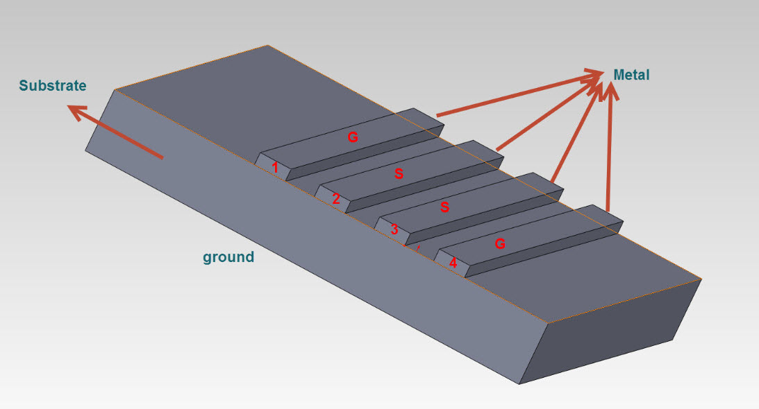
try to select twp points on your structure and then choose discrete port ,that is the suitable way for general cases
the waveguide only applied for flat structures like rectangular,circular and coaxial surfaces
Hello Contactor.
You can do the following:
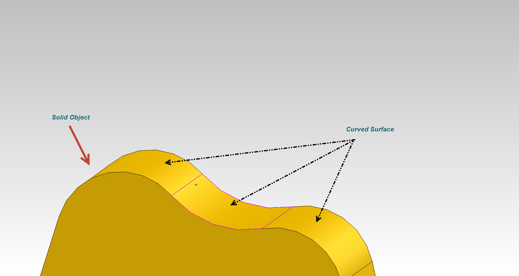
1) Extend the curved waveguide when it starts for a straight waveguide having same aperture size as the curved and define the Waveguide port excitation there.
2) Embed and then De-embed the waveguide port to make the excitation possible.
Best,
IH