nimeshasilva
Member level 1
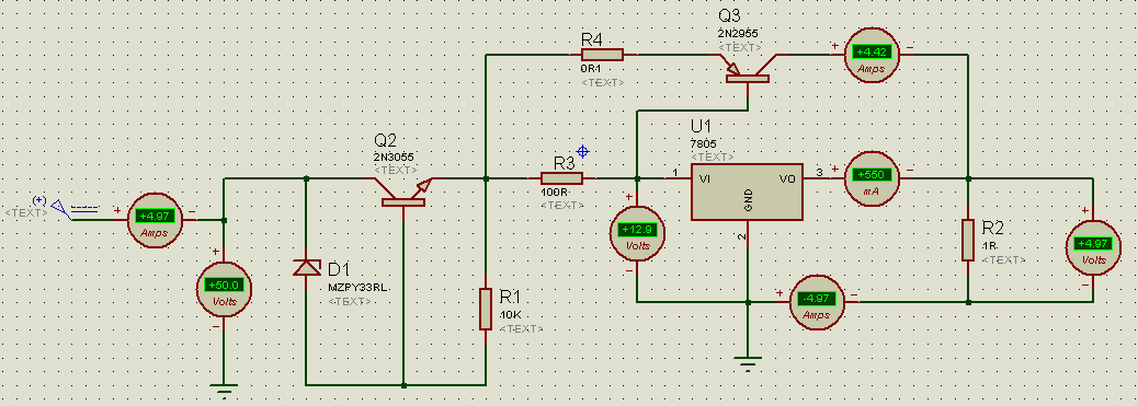
Can anybody please help me with this prob?? I need a 5V supply which the input supply should be around 50VDC and should be able to withstand around 5A. I tried the circuit below and it fails just after exceeding 2A. is anything wrong I have done with the circuit?? or I'm well appreciate, if anybody have a better circuit..
Thank you...
Thank you...