Continue to Site

Welcome to EDAboard.com

Welcome to our site! EDAboard.com is an international Electronics Discussion Forum focused on EDA software, circuits, schematics, books, theory, papers, asic, pld, 8051, DSP, Network, RF, Analog Design, PCB, Service Manuals... and a whole lot more! To participate you need to register. Registration is free. Click here to register now.

7805 high input voltage problem.

Status
Not open for further replies.

Qaisar Azeemi

Full Member level 5
Joined
Feb 11, 2011
Messages
315
Helped
16
Reputation
32
Reaction score
15
Trophy points
1,298
Location
Peshawar, Pakistan, Pakistan
Activity points
3,829
hi;

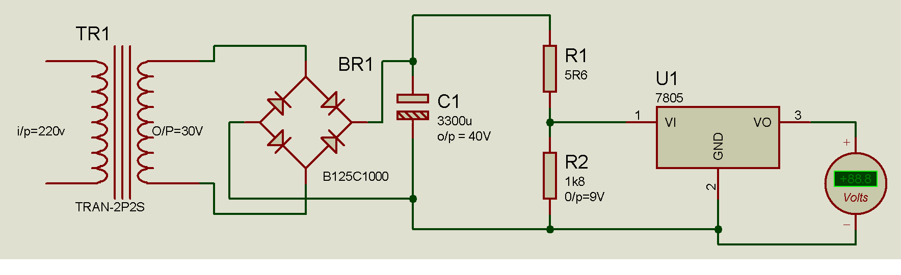
i am using 7805 and 7812 in my circuit. the DC input voltage out of Bridge and Capacitor is 40V DC but the maximum input voltage range is 35V for 78xx series.

when i connect voltage divider circuit to apply 9V at the input of 7805; The voltage divider circuit normally shown 9V but when i connect that node of voltage divider network to the input of 7805, the voltage dropped down to 3.1V :-( ... i repeatedly perform this experiment with many voltage divider networks consisting of different value combinations like 10k and 30k ... 1.8k and 5.6 k and 10M and 30M ohms but all the time it gave same problem.

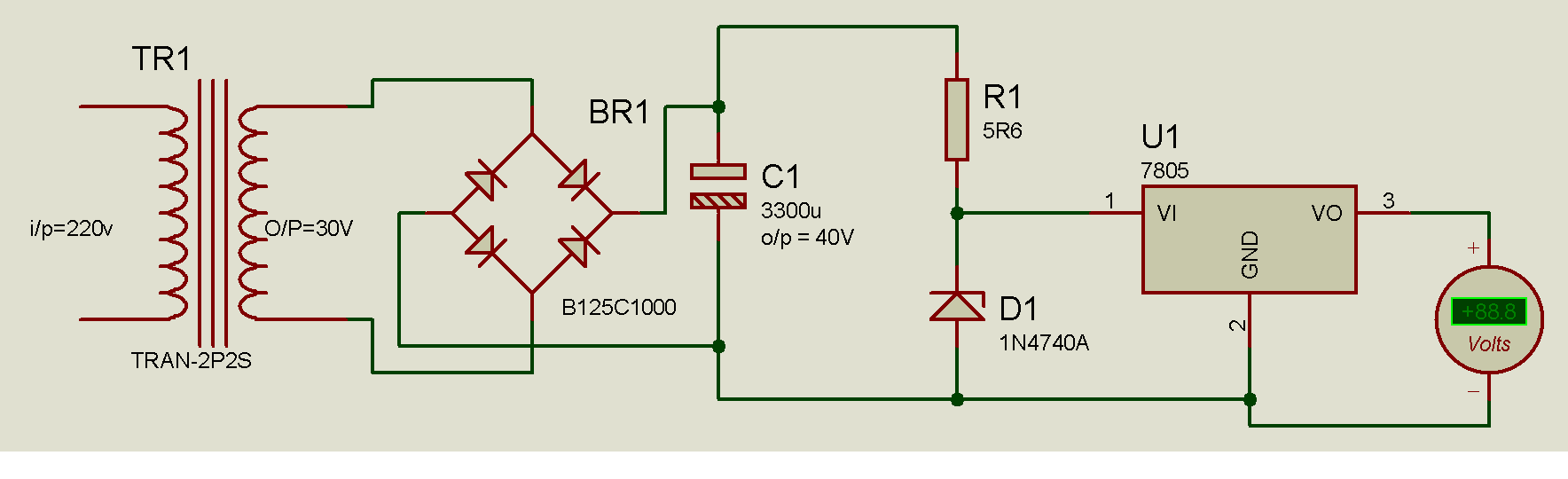
after that i connect the 10V zener diode in place of voltage divider network.. but it also gave the same effect..... :-(

please help me i want to provide 8 to 10V at the input of 7805 and 15 to 20v at the input of 7812 ICs.. But i have
the out from bridge and capacitor is 40V????

please tell me the solution.

Thank u.
 

You need to show your circuit to fix the problem. If it is simply a resistive voltage divider then that is a poor way of doing it. It will be very inefficient and waste a lot of power, depending on how much current you need. Mind you, a linear regulator from 40V down to 5V is never going to be very efficient!

I guess you have forgotten the current required by the regulator even when it is doing nothing - around 5mA or more. How much current do you need from the 5V supply?

A simple circuit like this would do. It would also help you move some of the power dissipation away from the 7805.

Keith.

91_1331038563.gif
 

I think you should use DC to DC down step switching converter for this.


Try this cheap MC34063


1331039082026-uploadscreenshot-dot-com.png
I set 1A in calculator, MC34063 can go to up 1,5A


Calculator address:
**broken link removed**


40V is max input voltage for this IC, you can try or search similar IC with higher input voltage.
 
Last edited:

Dear Qaisar,
First of all try to get some basics and read ohms law... please don't take it otherwise as i have no intention to offend you but to bring to your notice what basics you are missing .. actually voltage dividers are mainly used to scale down a high level voltage to some small voltage so that it can be sampled .. usually in voltage dividers the resistors used are several hundreds or kilo ohms in value... so the current the divider can supply is very low..so if you are going to load this output from divider then definitely voltages will drop to a voltage which is not at per the calculated voltage divider output voltages ( as per ohms law you can see that voltage drop across a resistor in series is directly proportional to current drawn through the resistor ) ...
SOLUTION
:- here you can use a raw pre regulator to step down the input voltages to a level under 7805 permissible input voltage specification.. try using a 180- 330 ohm 2 watt resistor and a 12 volts 1 watt zener at input of 7805.... proposed solution is what we uses in many of our designs.. hope that helps.

Best Regards,
Saifullah Khalid
 
You need to show your circuit to fix the problem. If it is simply a resistive voltage divider then that is a poor way of doing it. It will be very inefficient and waste a lot of power, depending on how much current you need. Mind you, a linear regulator from 40V down to 5V is never going to be very efficient!

I guess you have forgotten the current required by the regulator even when it is doing nothing - around 5mA or more. How much current do you need from the 5V supply?

A simple circuit like this would do. It would also help you move some of the power dissipation away from the 7805.

Keith.

91_1331038563.gif


theses are my circuits.


its by using voltage divider to get 9V at the input of 7805.. but the voltage at input of 7805 droped down to 2.1V....


its by using zener diode to get 10v at the input of 7805 ... but the voltage at input of 7805 droped down to 3.1V.

i need this to input a 5V DC to a simple circuit of 89c51, ADC0808 and 4X16 LCD display .. that i think will not need more than 1A.

i can't replace the transformer, bridge and capacitor coz i need it in my whole circuit... i want to provide 8 to 10v at the input of 7805 and similarly 15 to 20v at the input of 7812.. in order to make it functional with less heat dessipation.


secondly in your given figure of transistor with voltage divider bias once i performed an experiment with the transistors C828, C1383 and D313 and tried to get the voltages in the above configuration to get 12 v at the out put but how much the input at the collector up to 30V i increased the output at emitter remained fixed at 5V... it didn't increased from 5V anyway........
 

Dear Qaisar,
First of all try to get some basics and read ohms law... please don't take it otherwise as i have no intention to offend you but to bring to your notice what basics you are missing .. actually voltage dividers are mainly used to scale down a high level voltage to some small voltage so that it can be sampled .. usually in voltage dividers the resistors used are several hundreds or kilo ohms in value... so the current the divider can supply is very low..so if you are going to load this output from divider then definitely voltages will drop to a voltage which is not at per the calculated voltage divider output voltages ( as per ohms law you can see that voltage drop across a resistor in series is directly proportional to current drawn through the resistor ) ...
SOLUTION
:- here you can use a raw pre regulator to step down the input voltages to a level under 7805 permissible input voltage specification.. try using a 180- 330 ohm 2 watt resistor and a 12 volts 1 watt zener at input of 7805.... proposed solution is what we uses in many of our designs.. hope that helps.

Best Regards,
Saifullah Khalid

Thank you saifullah.

please upload the images of the circuit. how i connect the resistors and zener diode?

Can i use the following configuration using 1/3 inverting amplifier??


once i tried to use this circuit but cant get the required out put..... i was also providing less voltages at the output.... please guide me about that...
Thank you

---------- Post added at 19:49 ---------- Previous post was at 19:24 ----------

You can use also LM2575-5 or LM2576-5 Switching Regulators :

View attachment 70349

View attachment 70350


can it provide two outputs at a time.. i need 5V and 12V... or i have to use separate regulators for that???
and what is the formula to select program resistor??
 

Looking at your circuits you need to go back to basics and check your calculations.

Your circuit with a zener has 5.6 ohms to drop 40 down to 10V - that will take 5.3A and something will go up in smoke.

Your circuit using dropper resistors has 5.6 ohms & 1.8k and says 9V output but in reality the 5.6 ohms will drop almost nothing and you will still have nearly 40V on the 7805 input.

I am not 100% certain what you were trying to do with the transistor circuit but if you were driving the base with 5V then you will never get more than 5V out of the emitter no matter what the collector voltage is - that is the point of that sort of circuit.

Keith.
 

Qaisar
can it provide two outputs at a time.. i need 5V and 12V... or i have to use separate regulators for that???
and what is the formula to select program resistor??

Just use separate regulator like LM2575-5 and LM2575-12 or LM2576-5-12,....


With that your zener or resistor you will make just good source of heating element for colder days with smoke, nothing more.
 

Looking at your circuits you need to go back to basics and check your calculations.

Your circuit with a zener has 5.6 ohms to drop 40 down to 10V - that will take 5.3A and something will go up in smoke.

Your circuit using dropper resistors has 5.6 ohms & 1.8k and says 9V output but in reality the 5.6 ohms will drop almost nothing and you will still have nearly 40V on the 7805 input.

I am not 100% certain what you were trying to do with the transistor circuit but if you were driving the base with 5V then you will never get more than 5V out of the emitter no matter what the collector voltage is - that is the point of that sort of circuit.

Keith.

i am sorry i have connected 5.6k ohm resistor ... i mistakenly choose 5R6 ohms in proteous...... i wana drop the voltage down to nearly 9V. you can calculate using voltage divider formula 1.8k and 5.6k nearly provide 9V...
and yes i tried to switch the transistor using 5V output of 89c51...
you didn't gave the values of R1 and R2 in your circuit... and what transistor should i use for your given configuration?? should i use 2n2222 as the current flow is less than 1A.
Regards

---------- Post added at 20:20 ---------- Previous post was at 20:18 ----------

Qaisar


Just use separate regulator like LM2575-5 and LM2575-12 or LM2576-5-12,....


With that your zener or resistor you will make just good source of heating element for colder days with smoke, nothing more.

Can i not program it using different resistors just like we program LM317 linear regulator...
 

You can use if you need one regulator for 12V and then decsrease voltage to 5V with basic 7805.

Do you need both voltage at the same time?

What is current needed for 5V and what for 12V ?


You can use LM2576HVT-05 its 3A and input voltage can be up to 63V price about 5eur.


This is LM2576T-05 5V 3A price 1,5eur in my country, also LM2576T-12 12V 3A, for T input voltage can go up to 45V.

or

You can use LM2576T-ADJ adjustable 3A 1,23V-40V 1,5eur price.


I like LM2576S-5.0NOPB its TO-263 SMD 5V 3A 1,6eur price and I'm very happy with this.


In attachment is datasheet for LM2576T and LM2576HV:
 

Attachments

  • lm2576.pdf
    1.1 MB · Views: 113
Last edited:

The problem with 5.6k and 1.8k to drop the voltage is that even without any load on the regulator, the regulator will still take around 5mA. By my calculations, that means you will get just above 3V on the INPUT to the 7805.

If you use the simple transistor circuit I showed, use something like 5.6k and 1.8k as you were. The 2N2222 isn't a great choice as its Vceo is only 40V. I would suggest something with 60V to have a bit of safety.

If you want to take more than around 200mA from the transistor you may need to drop the resistors a bit.

Keith.
 

The LM2576 series offers a high-efficiency replacement for popular three-terminal linear regulators. It substantially reduces the size of the heat sink, and in some cases no heat sink is required. 50uA is standby current (quiescent current).


I whant to say that our edaboard friend Tahmid give me idea for this switching regulator in some earlier thread, and I must say I'm very happy with this regulator.
 
Last edited:

theses are my circuits.


its by using zener diode to get 10v at the input of 7805 ... but the voltage at input of 7805 droped down to 3.1V.

i need this to input a 5V DC to a simple circuit of 89c51, ADC0808 and 4X16 LCD display .. that i think will not need more than 1A.

above zener + resistor combination figure should work ok.. try 100/220/330 ohm 2 watt resistors (for R1) and zener (D1) can be any between 12-14 volts zener with at least one watt rating...
also check for your 4 X 16 LCD backlight current consumption .. that can be power sucker..just try checking it...

IMPORTANT : please try above zener + resistor combination on real board .. not on proteus...
 

above zener + resistor combination figure should work ok.. try 100/220/330 ohm 2 watt resistors (for R1) and zener (D1) can be any between 12-14 volts zener with at least one watt rating...

As I pointed out earlier, it would take 5.3A, assuming it worked long enough for you to see it. That is 159W into the resistor and 53W into the 1W zener diode.

With 5.6k instead of 5.6 ohms ... again, see my earlier posts.

Keith.
 

Keith maybe our friend cant answer, maybe zener make some visual effects in room. :smile: small smiley on this dark days.


I think there is no future in zener and resistor for this job. But should first experiment to learn.


My advice use some glasses to protect eyes when experimenting with this circuit.

Smart is to add some temperature protection in this device to protect real estate. Unattended usage of such device will be very risky!
 
Last edited:

My advice use some glasses to protect eyes when experimenting with this circuit.

I wear glasses and learned at the age of 10 the value of them. My optician couldn't work out what could have caused a blemish that looked like it had melted the glass of one of the lenses. A neon bulb in the mains with no series resistor will do that. At the time I didn't know much about electricity. I know a little more now.

Keith.
 

As I pointed out earlier, it would take 5.3A, assuming it worked long enough for you to see it. That is 159W into the resistor and 53W into the 1W zener diode.

With 5.6k instead of 5.6 ohms ... again, see my earlier posts.

Keith.

Dear Keith ,
I think you missed something..i already pointed out in above post to replace R1/D1 with 300++ ohms Resistor(2w/5w+) and a 12-14 V Zener with at least 1 watt rating... if the input is in range of 30 Vdc i think this raw solution will work... original poster can experiment with resistor values as per his requirement...
And TPETAR... NO IT WILL NOT PRODUCE ANY VISUAL EFFECT... seems you likes making fun of others.... this is the basic raw pre regulator solution which i thought was what original poster was looking for... .. and please don`t talk like that..i dont want to have any arguments etc... this is an open forum ..people here shares what ideas they have... its original poster who decides what suites him best...
one more question to TPETAR..did you ever tried using LM2575/LM2576 ... our experience with this particular switching regulator was very bitter as in our are ( southeast asia) many cloned chinese LM257x are sold... most of the time they failed... so the solution i suggest will also be able to withstand if there is some sudden voltage overshoot at input..but LM257x may not be able to bear any out of spec input voltages for even a short duration... rest i leave on the original poster .. he is free to chose any solution which he thinks suites his scenario the best... here after i will not comment....

BR
Saifullah Khalid
 
Last edited:

Dear Aashitech,

You wrongly understand all, you are just out of sense of humor and not purpose to fun someone.
I dont think, that my advice that he use protective glasses for protection when experimenting is fun.


LM2576 I used four times and plans more usage. I dont have problems with it. Maybe you buy some not original parts I dont know, maybe under rated inductor. I didnt have a problem I buy this from www.tme.eu I think that you miss something or you have bad parts when you try this. Probably you try one time this and you conclude that this not works. Your simptoms about LM2575/LM2576 like "cant handle input voltage,..." says me that you have bad parts, what I can do with that? to send you original part I dont know what you mean about that. You should try to search why your LM2575/LM2576 not work.
 

Status
Not open for further replies.

Part and Inventory Search

Welcome to EDABoard.com

Sponsor

Back
Top