Welcome to our site! EDAboard.com is an international Electronics Discussion Forum focused on EDA software, circuits, schematics, books, theory, papers, asic, pld, 8051, DSP, Network, RF, Analog Design, PCB, Service Manuals... and a whole lot more! To participate you need to register. Registration is free. Click here to register now.
i would like to do project related with smart grid and solar or wind energy.we are getting a fund of maximum 3 lakhs if we do so..we should submit our idea within march 25..please do post your ideas...
I would like to do projects related with the smart grid and solar or wind energy.we are getting a fund of maximum three lakhs if We do so .. We Should submit our ideas march Within 25 .. please do post your ideas ...
all that can we make through research, and requires a lot of money. project using solar energy in making it easier than the wind because if we use the wind we need for the regulator because the wind often changes (not necessarily). :-D
Hello to all,
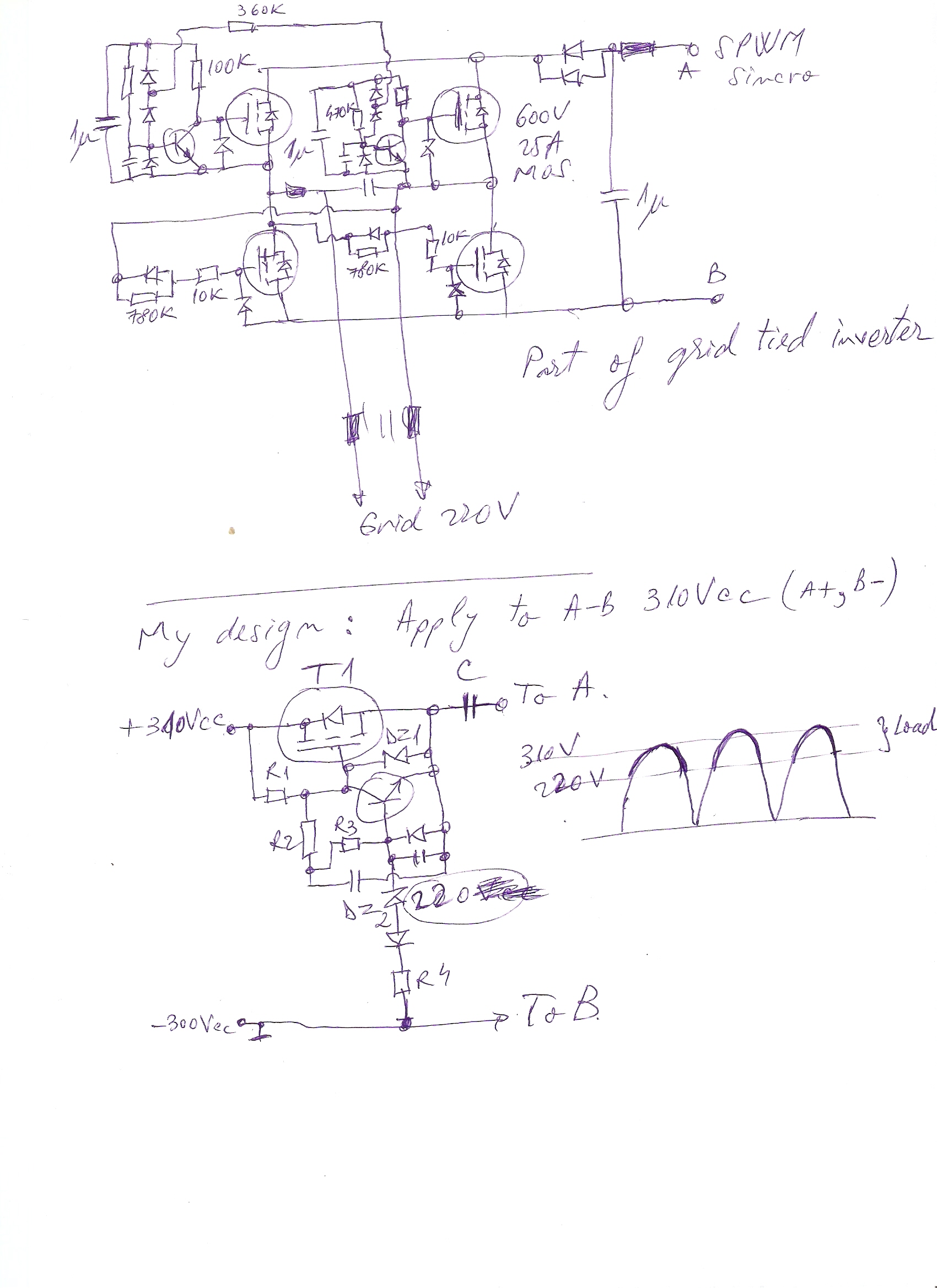
I'm not good at design in electronics but I became passionate about inverters. I found a logic operation of commercial grid inverter. I outlined in attachment my idea. It can be put into practice and if so worth the investment (cost compared to benefit)? I have not much time for testing.
i think your design is more appropriate for low voltage application. but i see you are using 600V mosfet, so i think probably you have higher DC bus. with higher DC bus, your switching will be susceptable to noise due to the floating reference of your upper switch. need to take better care of isolation. check TI chick TD350 and use a small isolation transformer to pass power to the gate drive section. also use a good opto coupler to pass digital signal, opto should have high CMMR and good input/output isolation (noise that travels up pin, across the plastic back and down pin on low voltage side). of course, this strategy is different if your focus is to build a million .. but as a one-off prototype you could design with quality. think also that your time of response (propegation delay between digital signal and actual ON/OFF of the mosfet). think of rise/fall time of your mosfet must be controllable at least during develompent because you will play a balance between noise, performance and heating with this feature.
then you must think of your failure modes. what if 600V dc bus is applied first, how do you guarantee no shoot-through when control voltage not presenent? what if during normal inverter use you were to suddenly lose control voltage? what if your gate driver power supply were to experience under voltage dip? brain storm on failure modes and find solution for each.
anyway, just some shouts from high up on the mountain
This site uses cookies to help personalise content, tailor your experience and to keep you logged in if you register.
By continuing to use this site, you are consenting to our use of cookies.
")