kamillas
Newbie level 4
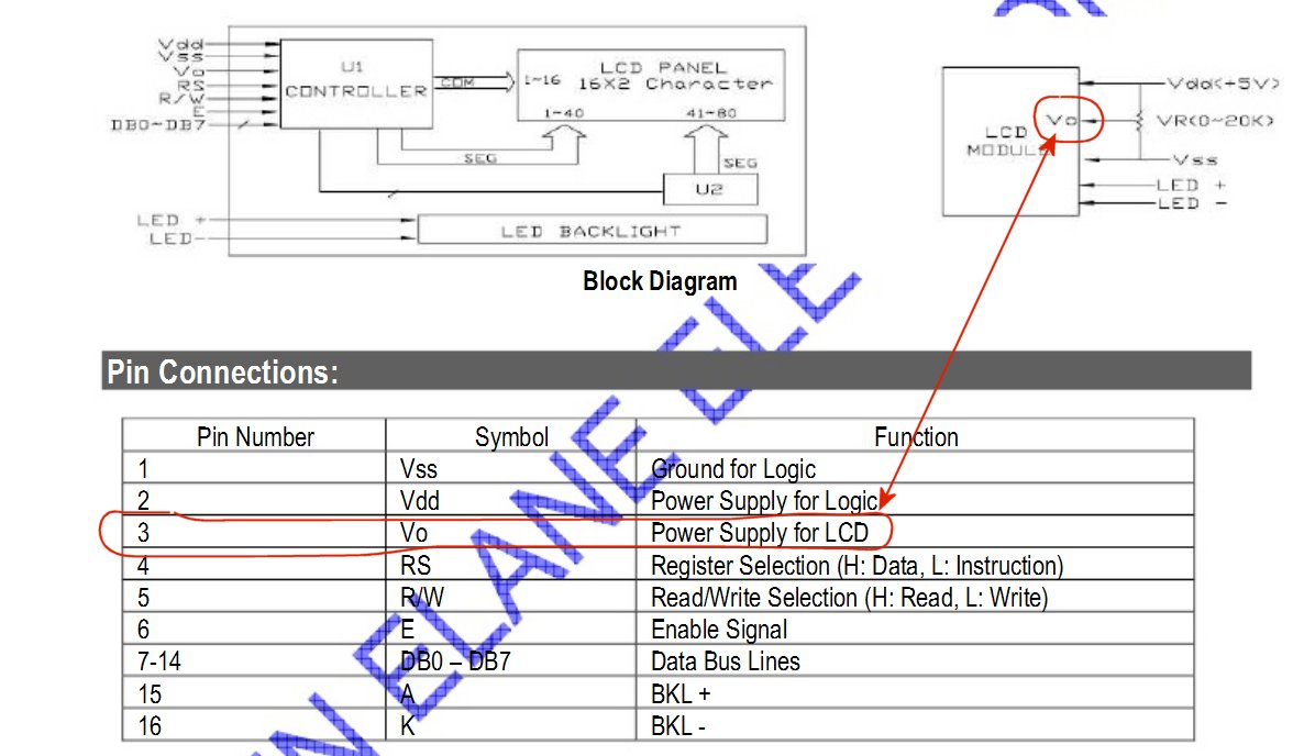
I made a circuit with a 2x16 LCD display, but in the simulation it works well, ie, it displays the word "temp", but in achieving it displays square! I have not resistors connected, and I do not think that's his problem, I connected this way,
I have connected every point, even I tested all outputs peak, he very well with the LEDs, means that all outputs are fine, but when I run the circuit I see that the tiles this is not a problem connecting, even I change LCD display 03 different types! this is not normal! really, I want you to help me
**broken link removed**
**broken link removed**
Driver LCD
// flex_lcd.c
// These pins are for the Microchip PicDem2-Plus board,
// which is what I used to test the driver. Change these
// pins to fit your own board.
#define LCD_DB4 PIN_D0
#define LCD_DB5 PIN_D1
#define LCD_DB6 PIN_D2
#define LCD_DB7 PIN_D3
#define LCD_E PIN_A1
#define LCD_RS PIN_A3
#define LCD_RW PIN_A2
// If you only want a 6-pin interface to your LCD, then
// connect the R/W pin on the LCD to ground, and comment
// out the following line.
#define USE_LCD_RW 1
//========================================
#define lcd_type 2 // 0=5x7, 1=5x10, 2=2 lines
#define lcd_line_two 0x40 // LCD RAM address for the 2nd line
int8 const LCD_INIT_STRING[4] =
{
0x20 | (lcd_type << 2), // Func set: 4-bit, 2 lines, 5x8 dots
0xc, // Display on
1, // Clear display
6 // Increment cursor
};
//-------------------------------------
void lcd_send_nibble(int8 nibble)
{
// Note: !! converts an integer expression
// to a boolean (1 or 0).
output_bit(LCD_DB4, !!(nibble & 1));
output_bit(LCD_DB5, !!(nibble & 2));
output_bit(LCD_DB6, !!(nibble & 4));
output_bit(LCD_DB7, !!(nibble & 8));
delay_cycles(1);
output_high(LCD_E);
delay_us(2);
output_low(LCD_E);
}
//-----------------------------------
// This sub-routine is only called by lcd_read_byte().
// It's not a stand-alone routine. For example, the
// R/W signal is set high by lcd_read_byte() before
// this routine is called.
#ifdef USE_LCD_RW
int8 lcd_read_nibble(void)
{
int8 retval;
// Create bit variables so that we can easily set
// individual bits in the retval variable.
#bit retval_0 = retval.0
#bit retval_1 = retval.1
#bit retval_2 = retval.2
#bit retval_3 = retval.3
retval = 0;
output_high(LCD_E);
delay_cycles(1);
retval_0 = input(LCD_DB4);
retval_1 = input(LCD_DB5);
retval_2 = input(LCD_DB6);
retval_3 = input(LCD_DB7);
output_low(LCD_E);
return(retval);
}
#endif
//---------------------------------------
// Read a byte from the LCD and return it.
#ifdef USE_LCD_RW
int8 lcd_read_byte(void)
{
int8 low;
int8 high;
output_high(LCD_RW);
delay_cycles(1);
high = lcd_read_nibble();
low = lcd_read_nibble();
return( (high<<4) | low);
}
#endif
//----------------------------------------
// Send a byte to the LCD.
void lcd_send_byte(int8 address, int8 n)
{
output_low(LCD_RS);
#ifdef USE_LCD_RW
while(bit_test(lcd_read_byte(),7)) ;
#else
delay_us(60);
#endif
if(address)
output_high(LCD_RS);
else
output_low(LCD_RS);
delay_cycles(1);
#ifdef USE_LCD_RW
output_low(LCD_RW);
delay_cycles(1);
#endif
output_low(LCD_E);
lcd_send_nibble(n >> 4);
lcd_send_nibble(n & 0xf);
}
//----------------------------
void lcd_init(void)
{
int8 i;
output_low(LCD_RS);
#ifdef USE_LCD_RW
output_low(LCD_RW);
#endif
output_low(LCD_E);
delay_ms(15);
for(i=0 ;i < 3; i++)
{
lcd_send_nibble(0x03);
delay_ms(5);
}
lcd_send_nibble(0x02);
for(i=0; i < sizeof(LCD_INIT_STRING); i++)
{
lcd_send_byte(0, LCD_INIT_STRING);
// If the R/W signal is not used, then
// the busy bit can't be polled. One of
// the init commands takes longer than
// the hard-coded delay of 60 us, so in
// that case, lets just do a 5 ms delay
// after all four of them.
#ifndef USE_LCD_RW
delay_ms(5);
#endif
}
}
//----------------------------
void lcd_gotoxy(int8 x, int8 y)
{
int8 address;
if(y != 1)
address = lcd_line_two;
else
address=0;
address += x-1;
lcd_send_byte(0, 0x80 | address);
}
//-----------------------------
void lcd_putc(char c)
{
switch(c)
{
case '\f':
lcd_send_byte(0,1);
delay_ms(2);
break;
case '\n':
lcd_gotoxy(1,2);
break;
case '\b':
lcd_send_byte(0,0x10);
break;
default:
lcd_send_byte(1,c);
break;
}
}
//------------------------------
#ifdef USE_LCD_RW
char lcd_getc(int8 x, int8 y)
{
char value;
lcd_gotoxy(x,y);
// Wait until busy flag is low.
while(bit_test(lcd_read_byte(),7));
output_high(LCD_RS);
value = lcd_read_byte();
output_low(lcd_RS);
return(value);
}
#endif
Here's a test program for the Flex driver:
Code:
#include <16F877.H>
#fuses XT, NOWDT, NOPROTECT, BROWNOUT, PUT, NOLVP
#use delay(clock = 4000000)
#include "flex_lcd.c"
//==========================
void main()
{
lcd_init(); // Always call this first.
lcd_putc("\fHello World\n");
lcd_putc("Line Number 2");
while(1);
}
")