Continue to Site

Welcome to EDAboard.com

Welcome to our site! EDAboard.com is an international Electronics Discussion Forum focused on EDA software, circuits, schematics, books, theory, papers, asic, pld, 8051, DSP, Network, RF, Analog Design, PCB, Service Manuals... and a whole lot more! To participate you need to register. Registration is free. Click here to register now.

FPGA transparent latches

Status
Not open for further replies.

shaiko

Advanced Member level 5
Joined
Aug 20, 2011
Messages
2,644
Helped
303
Reputation
608
Reaction score
297
Trophy points
1,363
Activity points
18,302
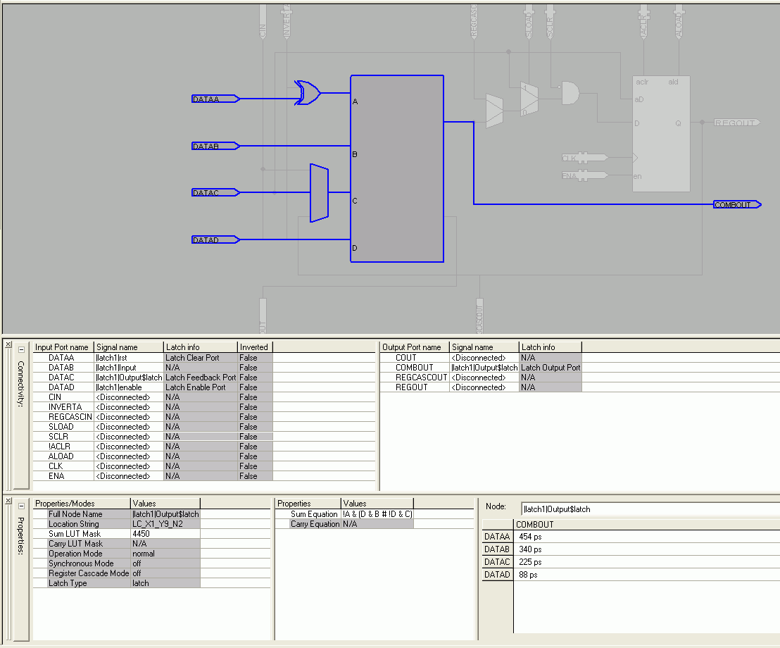
Most (if not all) FPGAs/CPLDs have only synchronous D flop flops.
So...How are transparent latches implemeted ?
Is it done by some kind of manipulation on the D flip flop ? If so, what ?
 

Asynchronous latches are mostly implemented as "logic loop", feeding back a combinational LE's output to an input of either the same LE or a different one. Synthesis tools are often warning about latch synthesis, but they are obviously required in some cases, e.g. as address latches for an asynchronous multiplexed data bus.

The most simple way to see how it's implemented is to code a latch and review the gate level netlist.
 
  • Like
Reactions: shaiko

    shaiko

    Points: 2
    Helpful Answer Positive Rating
The most simple way to see how it's implemented is to code a latch and review the gate level netlist.
After you've done that, the most simple way to watch the latch fail is to use a heat gun or cold spray to change the temperature of the device. The more painful way is if the failure doesn't show up until you're trying to ship large volumes. Not to say that a latch in an FPGA or CPLD can't be done...but it is very easy to not get it done right and think that you have.
 

process (rst,input, output, enable) is
begin
if rst = '1' then
output <= '0';
elsif enable = '1' then
output <= input;
end if;
end process;

will the above code inffer a latch ?
 

process (rst,input, output, enable) is
begin
if rst = '1' then
output <= '0';
elsif enable = '1' then
output <= input;
end if;
end process;

will the above code inffer a latch ?

Yes it will infer a latch. It may or may not infer a latch that actually works. Whether it does or not will depend in part on the chosen device family. Based on your other posts in the forum, I'm assuming that your target is a CPLD (presumably with the common and/or array). On that assumption, a working latch that is functionally equivalent can be inferred with the following code instead...but only if you disable logic optimizations for this signal.
Code:
output <= (not(rst) and enable and input)
          or  (not(rst) and not(enable) and output)
          or  (not(rst) and input and output);
If you don't disable logic optimizations, the third term will be reduced out since it is redundant (but absolutely necessary to handle the race condition when 'enable' switches from '1' to '0'). In that case it is highly likely that your latch will eventually fail under some combination of temperature, voltage or production lot conditions. Since your original code includes no such cover terms, it will be susecptible to a race condition that also will eventually cause it to fail for the same reason. On the other hand, since it appeared from your other posts that this will be a very rarely used latch having to do with waking up a processor, it is also quite possible that your original code would work only because the design won't be switching the enable that often. But, in any case, better to be safe than sorry.

Kevin Jennings
 
Last edited:
  • Like
Reactions: shaiko

    shaiko

    Points: 2
    Helpful Answer Positive Rating
I basically agree about the risk of unpredicatable behaviour for arbitrary latch constructions.

Referring to FPGA design, the present example (from post #4) can be synthesized in a single logic element with well-controlled behaviour. It's also obvious, that at least Altera Quartus is aware of the latch functionality and shows it in an additional "Latch Info" column in the resource property editor. I'm rather confident of synthesis tool's capability to produce reliable code for simple latches like the present one, including those that need to be added by the compiler itself in special cases.

Complex latch constructs with feedback terms spanning multiple LE's and thus affected by routing delays shouldn't be needed in designs with limited asynchronous logic, I suppose.

CPLD synthesis uses a different, less powerful tool in Altera Quartus. I remember to have seen dubious behaviour of asynchronous constructs with Quartus predecessor MAX Plus and I would also check recent Quartus CPLD gate level results.

 
  • Like
Reactions: shaiko

    shaiko

    Points: 2
    Helpful Answer Positive Rating
A transparen latch is safer in FPGA because at least Altera and Xilinx guarantee that there is no glitch on the LUT output if only one input changes.
For CPLD, it is important to verify that you don't get the problem described above by K-J.
 
  • Like
Reactions: shaiko

    shaiko

    Points: 2
    Helpful Answer Positive Rating
Status
Not open for further replies.

Similar threads

Part and Inventory Search

Welcome to EDABoard.com

Sponsor

Back
Top