Vermes
Advanced Member level 4

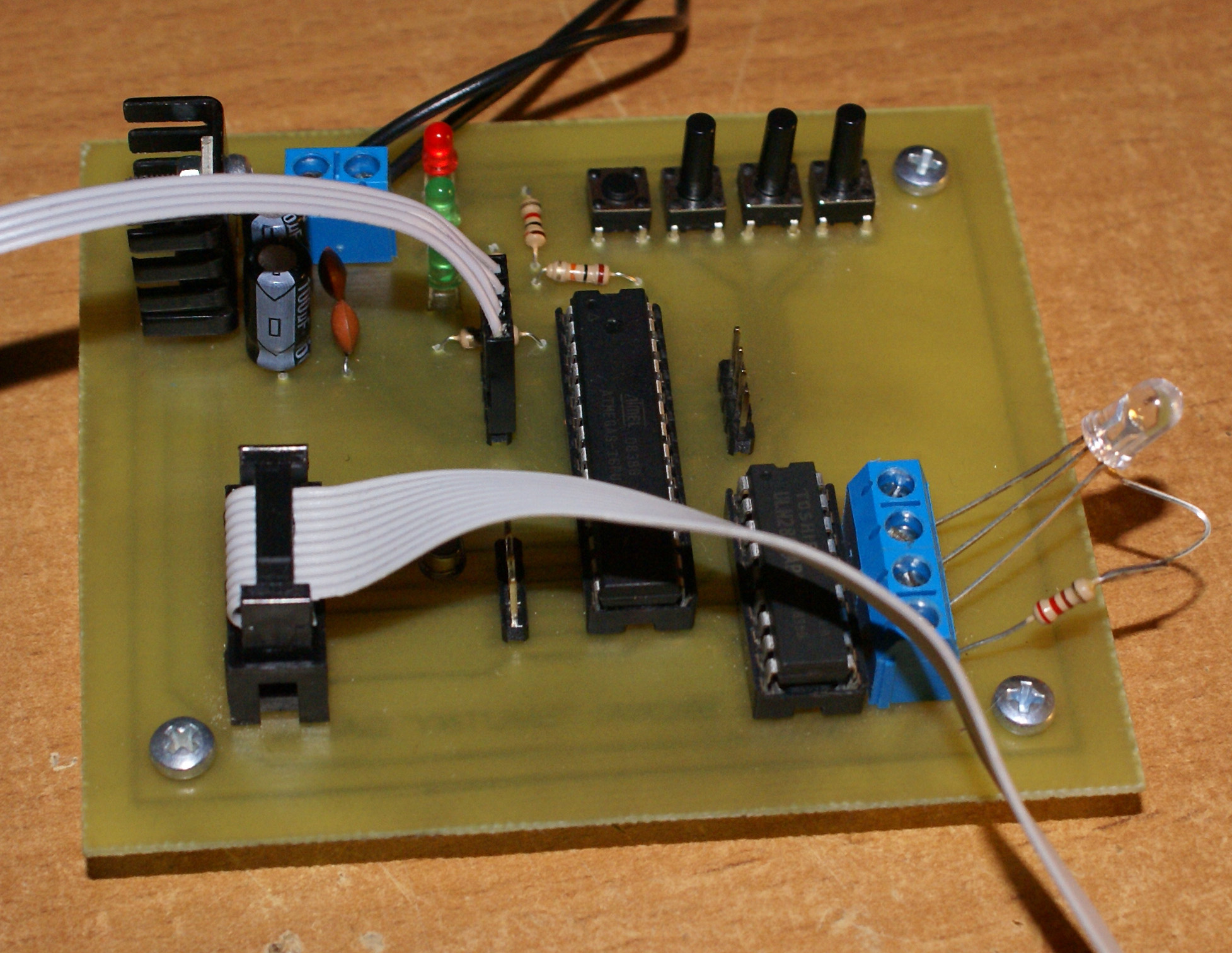
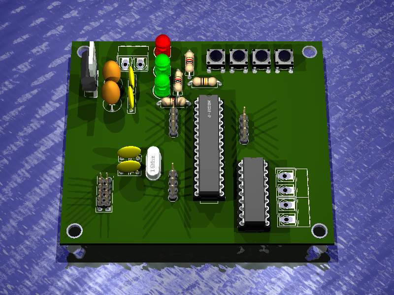
Presented device is a 40 RGB diodes driver. The construction is quite simple, there are few elements on the board:
- stabilizer LM7805 + heat sink + voltage filtering capacitors
- microcontroller Atmega8
- ULN2803AG
- quartz 16MHz
- system MAX232 connected on tape
The driver is to control 40 RGB diodes on common wires.
Assumptions:
- ability to connect 40 RGB diodes
- remote control by the program from touch panel
- different lighting programs consisted of:
- PWM (gradual transition of colours)
- possibility to turn on a single colour of diode – with its adjustable brightness
- police lights
- all colours in turn
- possibility to change the speed of effects (time of transition, blinking, etc.)
- possibility to connect different diodes
- possibility of emergency control using buttons
System ULN2803 were used to control diodes because of they are really easy to connect, quick to be changed when damaged and their maximum current consumption of 500mA.
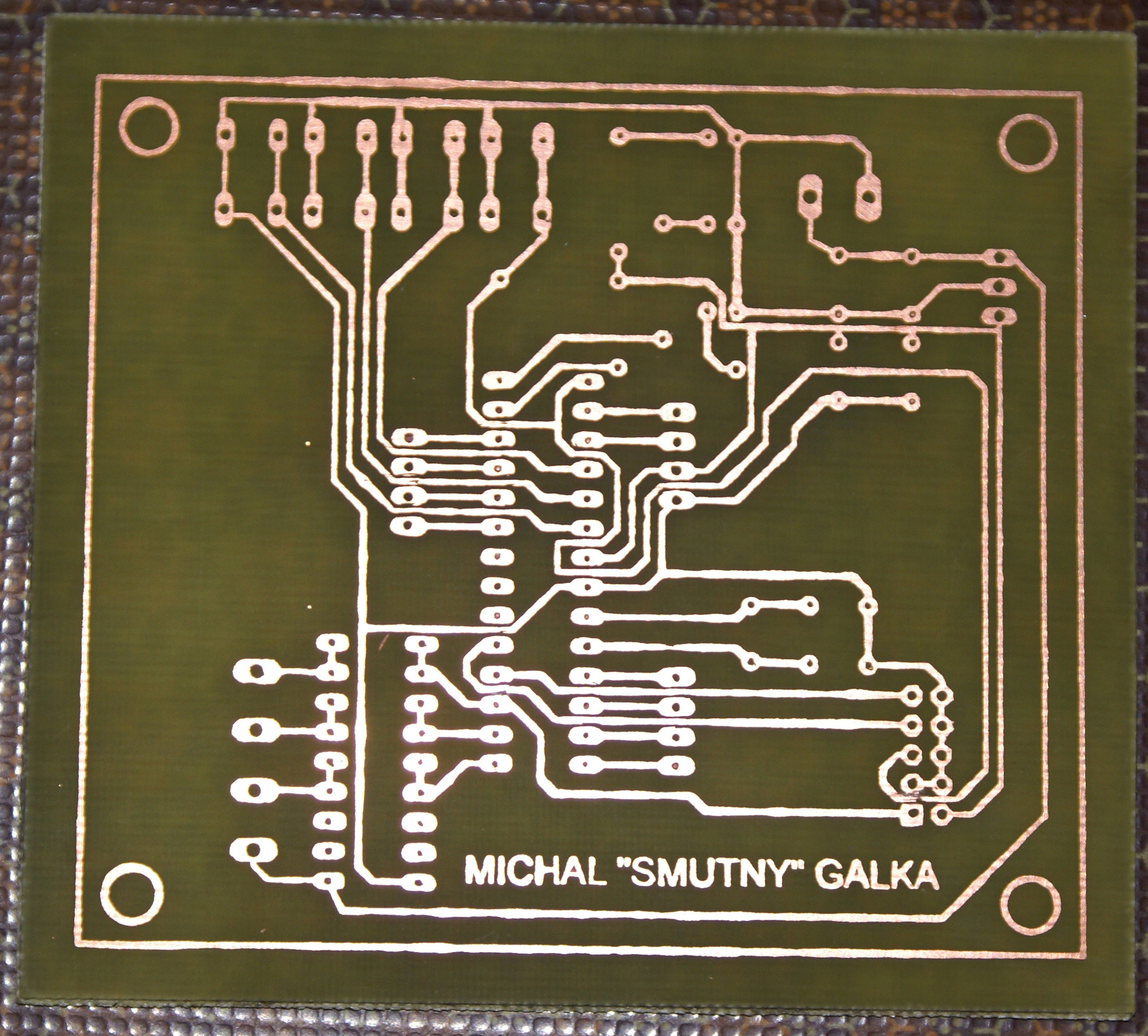
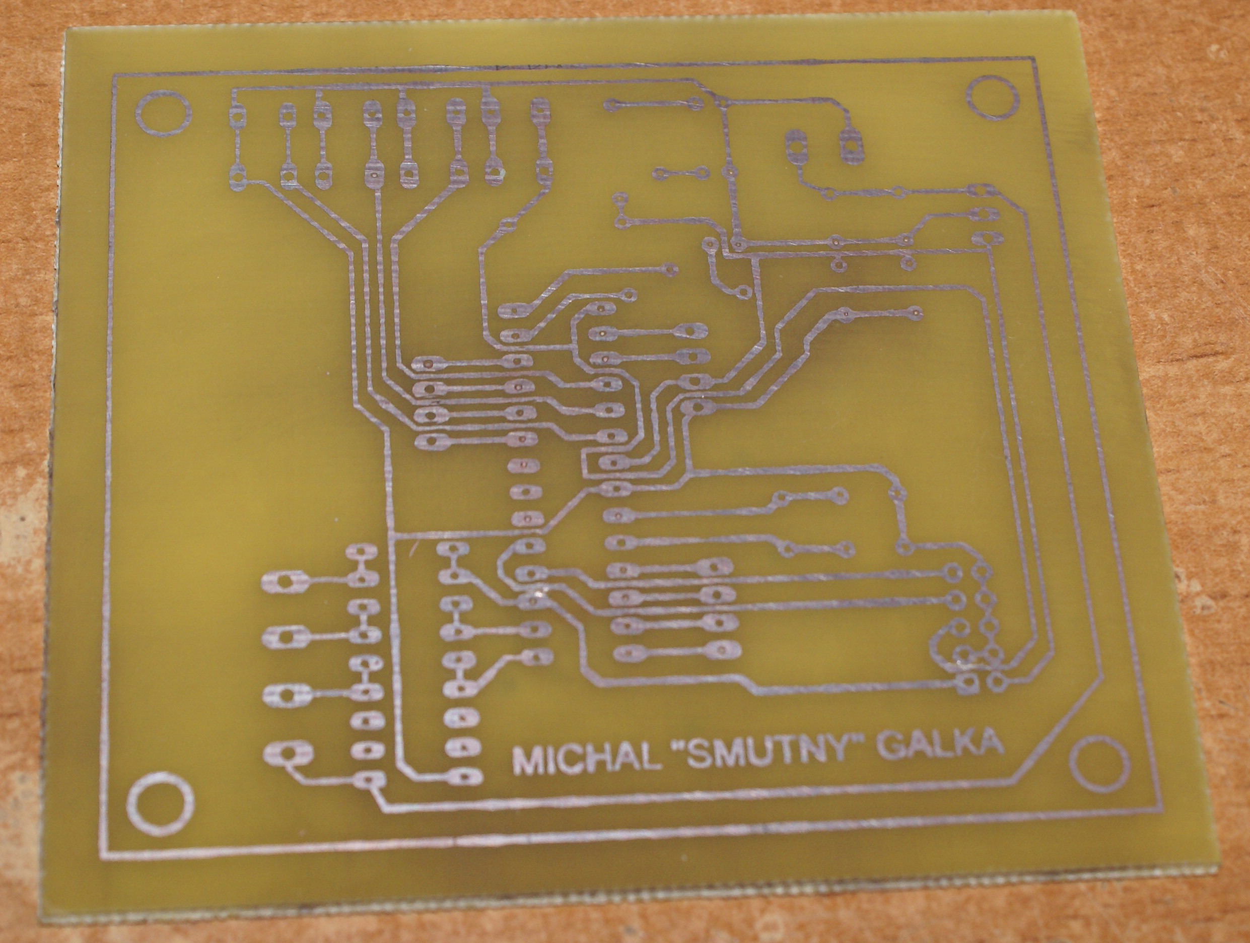
The board was made by thermal transfer method, then chemical tin covered. Pictures show the board before and after covering.
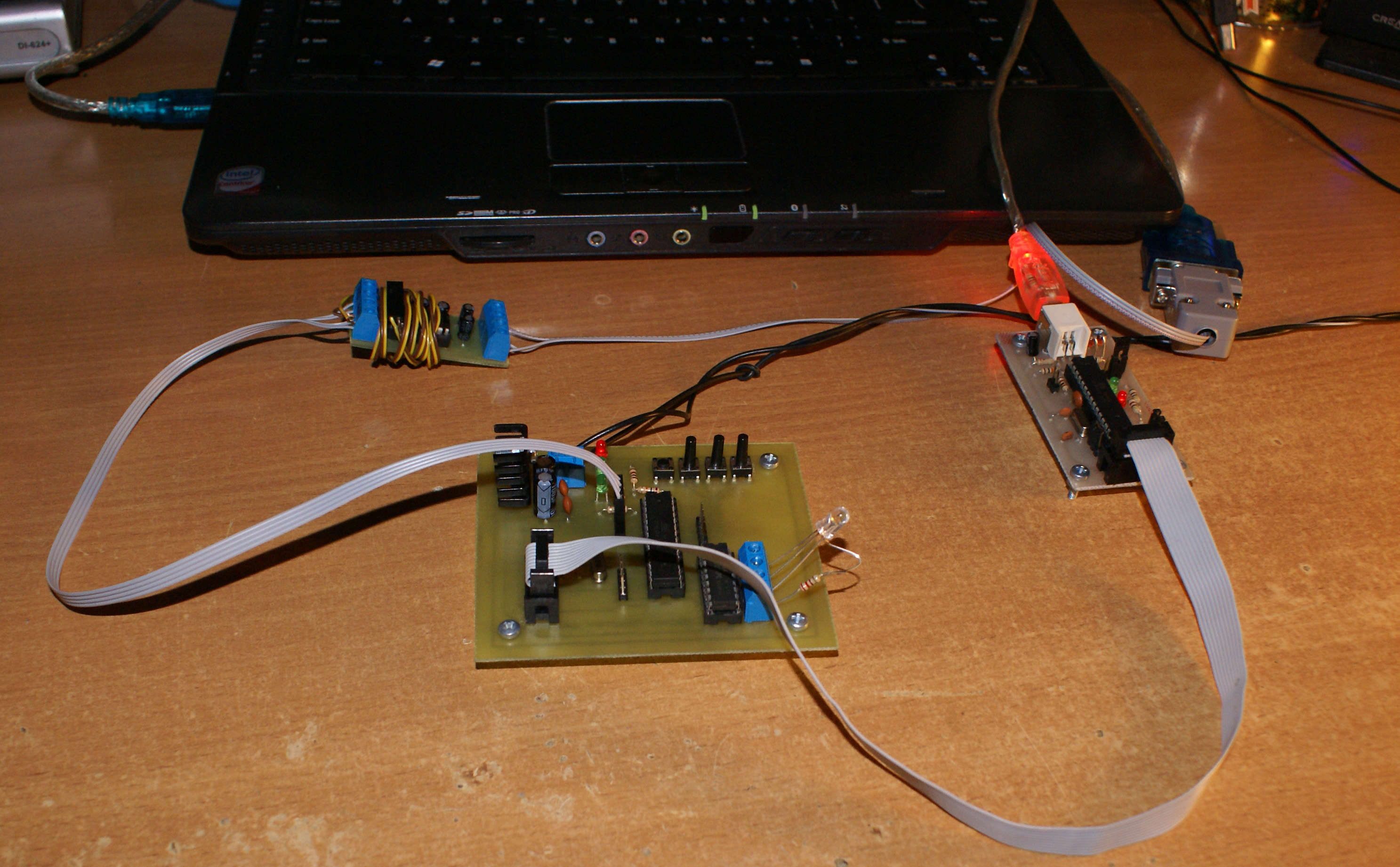
Then holes were drilled, elements soldered and the program uploaded.


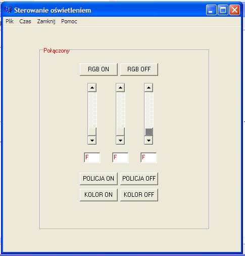
The program for the driver was written in Bascom, and the program for the computer in C++ Builder. Below you can see a screen of running the control program.
Remember to declare Timer2 correctly, because mistakes can cause problems with using output OCR2 in Atmega8. Below there is the correct configuration to control PWM from OCR2 output.
Code:
Config Timer1 = Pwm , Prescale = 1 , Pwm = 8 , Compare A Pwm = Clear Down , Compare B Pwm = Clear Down
Config Timer2 = Pwm , Pwm = On , Prescale = 1 , Compare Pwm = Clear Down

'Wyjścia PWM:
Pwm1a = 0
Pwm1b = 0
Ocr2 = 255
Video of the program working:
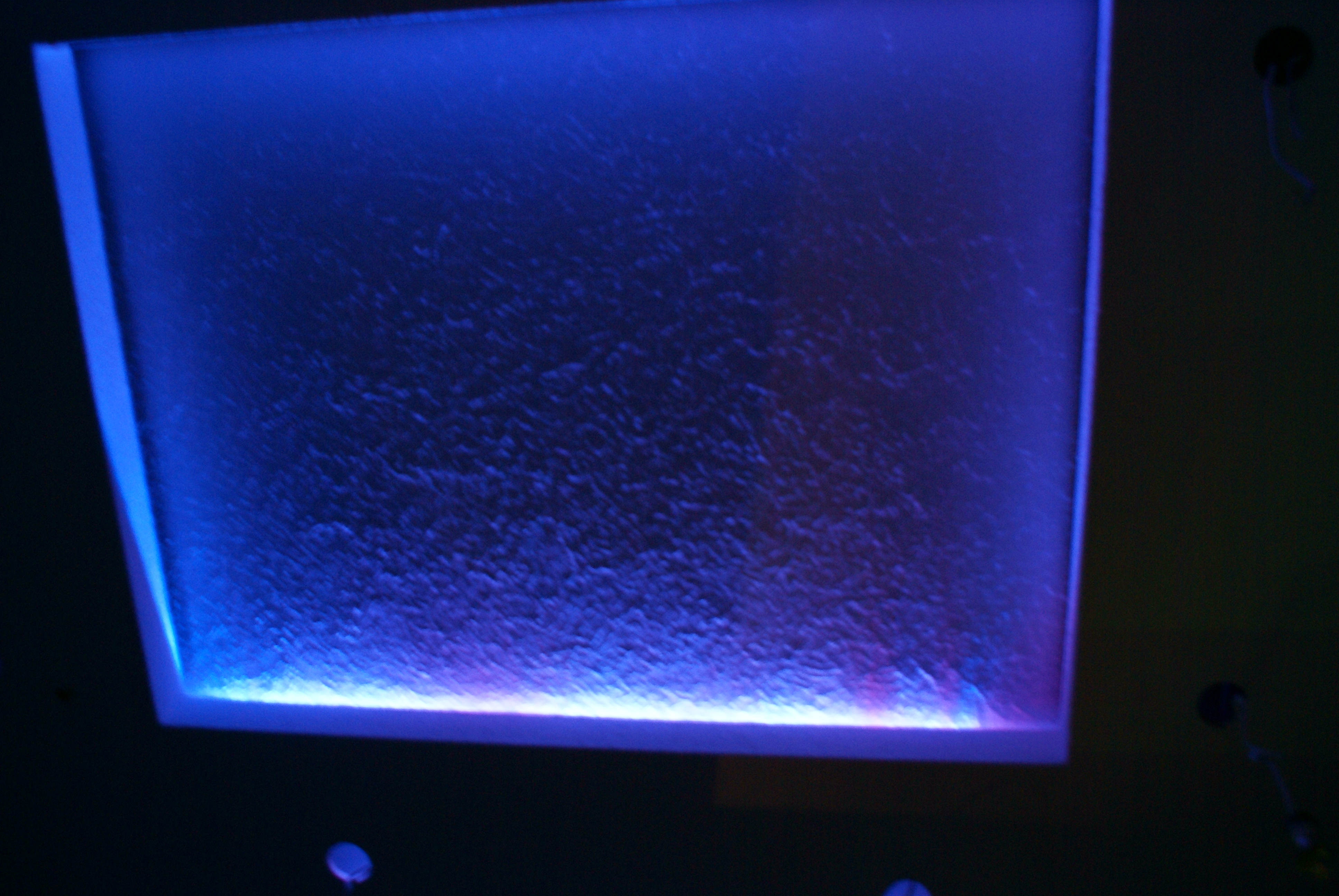
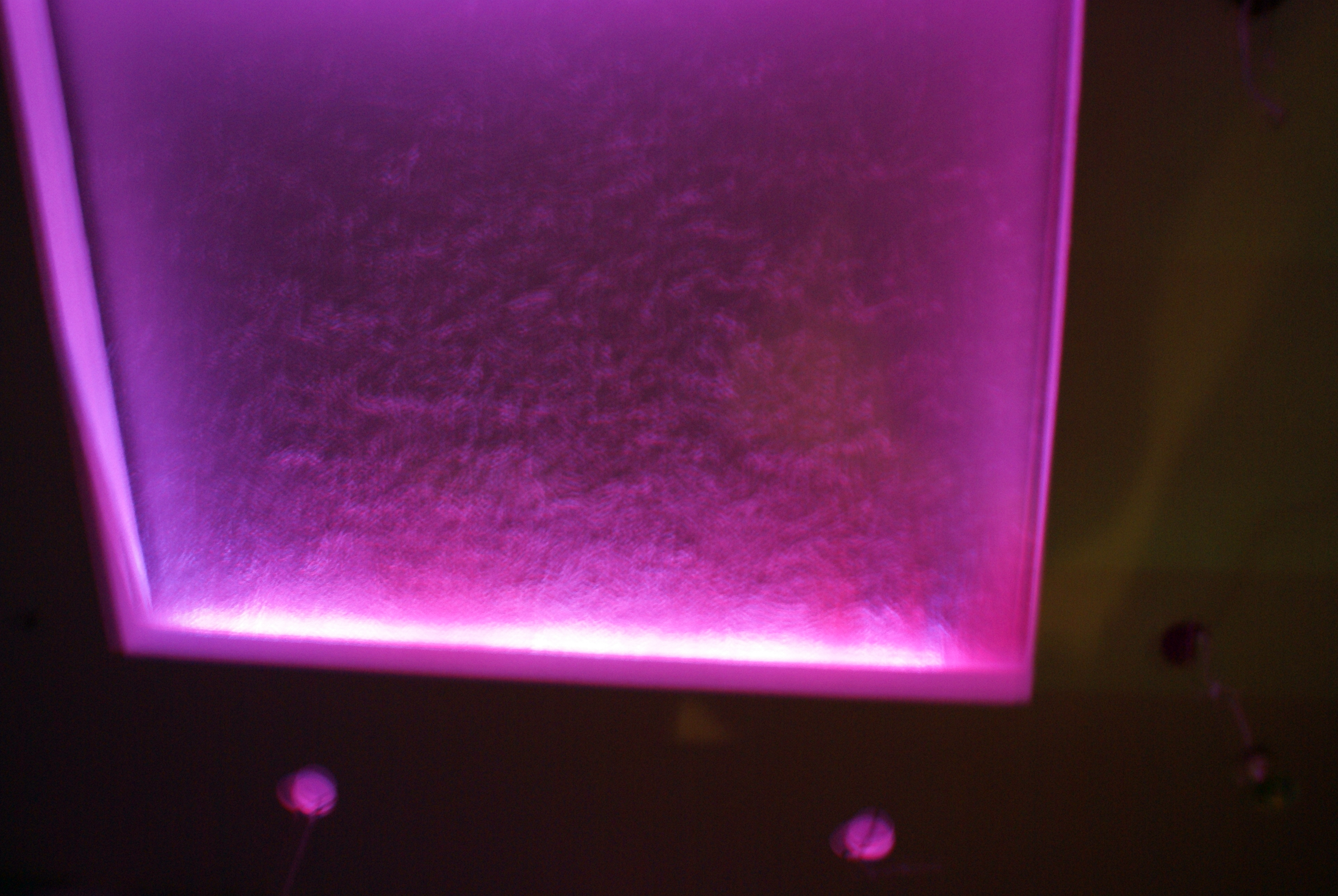
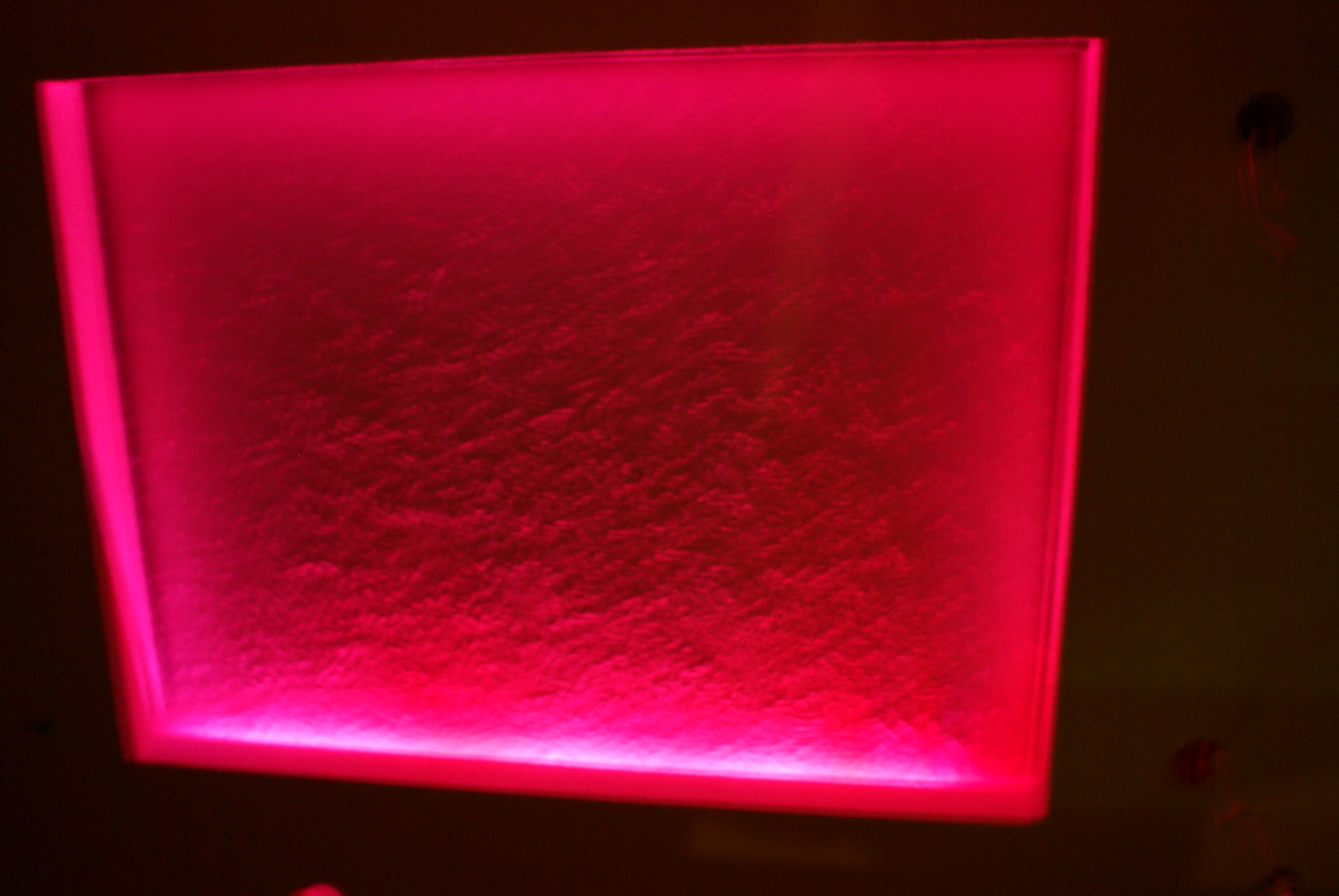
Pictures of tests:
Link to original thread (useful attachment) – Sterownik oświetlenia - Sterownik diod RGB