Vermes
Advanced Member level 4
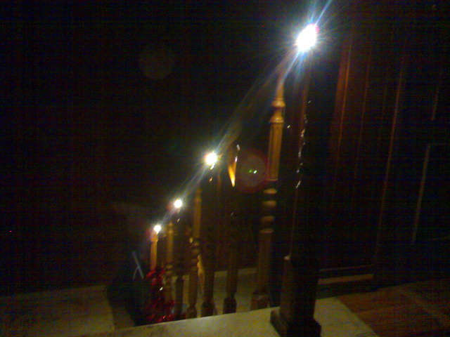
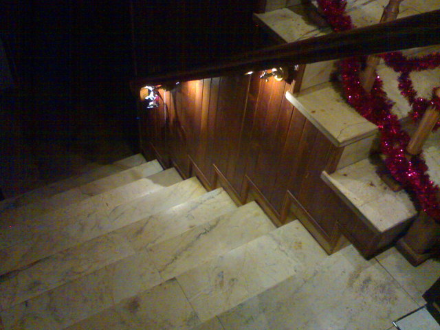
Light of presented device is produced by 8 LEDs placed under the handrail, 3 in the lower part, 3 in the upper part and 2 on the mezzanine.
How it works:
When you go upstairs, the phototransistor (infrared barrier) detects that, then the LEDs light up smoothly, according to one of three fixed patterns:
- lighting up each LED in turn
- lighting up the first lower part, then the mezzanine, and at the end the upper part
- lighting up all the LEDs at once
LEDs do not light up suddenly, but they are smoothly lightened using eight software channels of PWM. After 30 seconds from the last response of the sensor, all the LEDs darken and switch off.
If you go upstairs, the LED lighting is animated from the bottom, begins with the lighting of LEDs that are closely and continuously going up. If you go downstairs, this pattern is reversed and the LED are lit up from above.
The first and last LED, which is at the top and the bottom, light all the time with 2 percent fill, enough to reach the the edge of the stairs and then all the LEDs light up.
To save power, the infrared LEDs do not illuminate all the time, but blink around 13 times per second with 33 percent fill, and the sensors check the status only during the illumination.

The time of lighting for the video was set to 4 seconds, it normally should be 30 seconds.
Driver:
- microcontroller Attiny2313 with an external oscillator set to 8MHz
- 8 outputs for LEDs (transistors BC817)
- 4 outputs for infrared LEDs (BC817)
- 4 inputs for phototransistors (darlington BCV27, only 2 inputs are currently used in the program)
- external power supply 5V (or more after soldering stabilizer 7805)
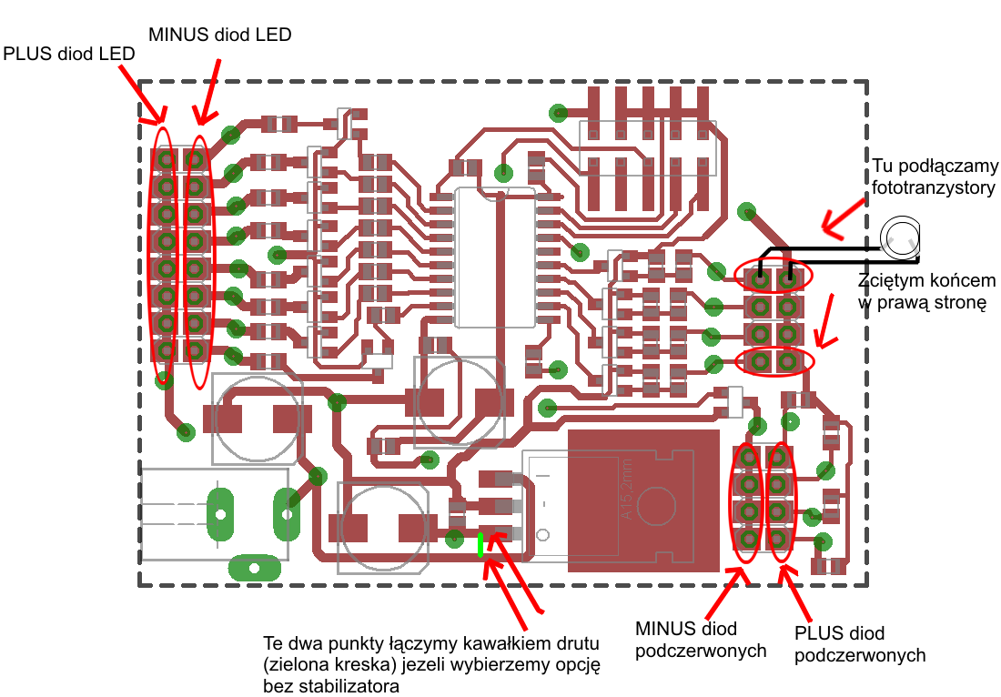
A pair of IR LED-phototransistor should be placed at the top and bottom of the stairs in a way that they can „see” each other.
Program:
Program was written in C (GCC) uses an interrupt to generate 8 channels PWM. Patterns, according to which the LEDs are lit, were defined in three tables (names from data_zapal).
You can define your own patterns, depending on your needs. The following values in each row are brightnesses of each of eight LEDs. Each row is the state of LED in time. Brightness of LEDs is smoothly changed between the values of each row.
Darkening the LEDs is defined in table data_zgas_1, just remember that in the last row of the table, the first and last LED should have a small value e.g. from 2 to 5, so those two LEDs always light when the rest switches off.
You should set the internal clock to a frequency of 8MHz for the proper work of the program. If you use programmer USBASP, you can achieve this by giving the following command from the command line:
avrdude -p attiny2313 -c usbasp -U lfuse:w:0xe4:m -U hfuse:w:0xdf:m -U efuse:w:0xff:m
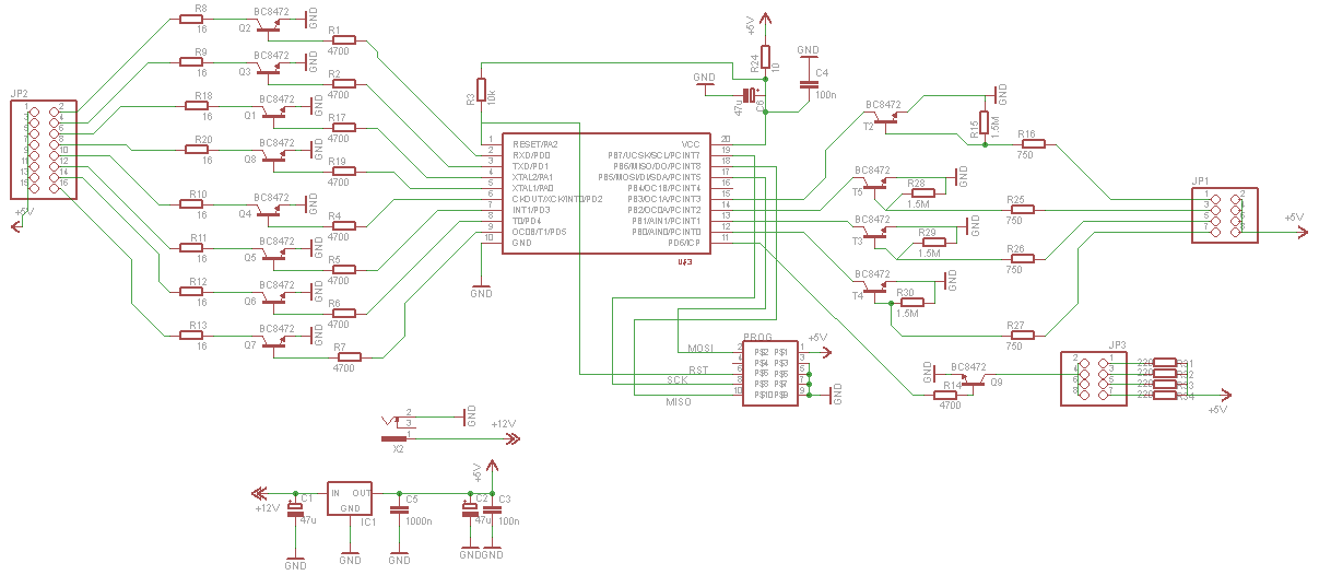
Scheme:
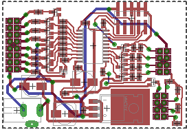
Board:
Two-layers board was made so it can be quite easily home made.
Most SMD elements, only connectors are threaded, with the exception of programmer connector.
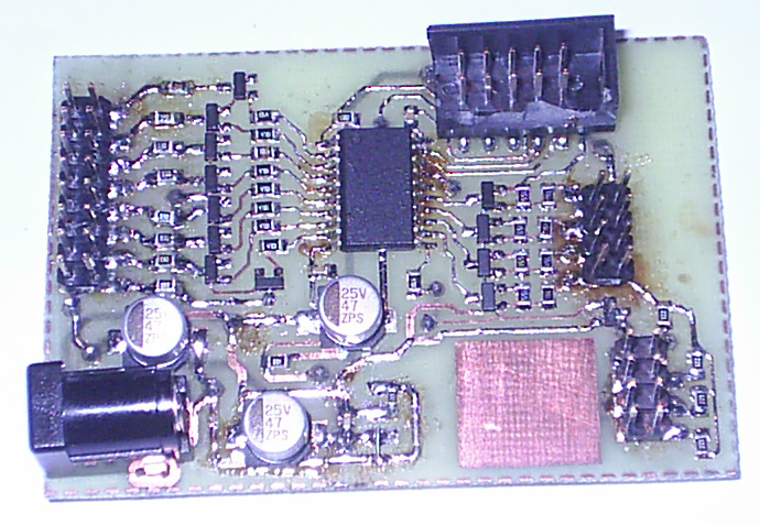
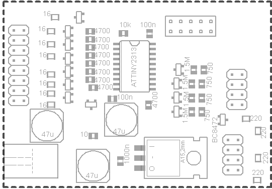
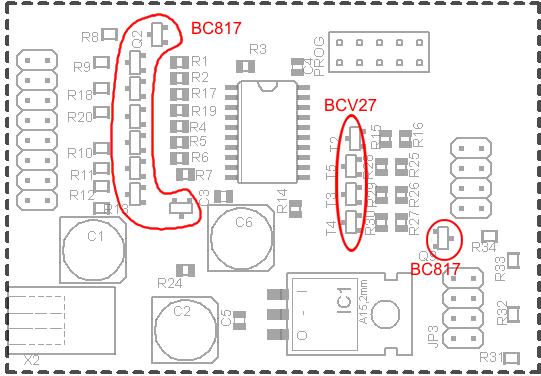
When soldering, please pay attention to the transistors. For LEDs they are BC817, but for phototransistors they are BCV17. Below there are pictures with names of elements and their values.
Below you can see a ready made set for board lamination and digestion. It should be printed and bent so that both of the holes overlap. You do not have to make a mirror, it is already made.
The picture must be printed with resolution of 600dpi in order to achieve appropriate size of the board.

Power supply:
Power supply preferably from the plug, necessarily stabilized, 5V. In this case, do not solder the stabilizer 7805, but connect pads indicated in the picture further down by a piece of wire or a drop of tin.
Another option, if you do not have a proper power supply, is to solder the stabilizer and power of the system from a greater voltage, e.g. 9-12V, but then you should screw a plate or heat sink to the stabilizer to dissipate heat. Current efficiency of the stabilizer is about max 1A, so in this case, the LEDs are unlikely to be stronger than 100mA.
The LEDs and their resistors:
Maximum efficiency of transistors at the outputs is 500mA, but it is better not to use them to their limits.
That is why you should use LEDs with a maximum current from 20mA to 250mA.
To select the resistors, you can use a LED calculator such as: .
Type the 5V supply voltage, the light voltage 2v for red, 3v for white, green and blue, and the required current in mA.
And the best just use a potentiometer and ammeter, then you choose the resistors accurately.
Sensors and IR diodes:
Phototransistors and IR diodes working in the range of 940nm were used. When connecting, pay attention in order not to connect them conversely – there are 3 ways to connect them and only one is correct. When you connect the diode conversely, it just does not light. Phototransistor connected conversely works very poorly, the range will drop below 10cm.
If the sensitivity turns out to be too low, then you can connect e.g. two or three phototransistors in parallel instead of one. You can also connect more IR diodes in parallel, just correspondingly reduce the resistors.
Used phototransistors react to the day light and light of normal bulbs, so you can put a piece of pipe on them so they can see the IR diode light.
The effect will be that the sensor will not enable the lighting.
List of elements:
- LIRT3B-940 – phototransistor x2
- LIRED3B-940 – IR diode x2
- BC817-40 – transistor for LEDs x9
- Attiny2313-20SU x1
- BHT10S – connector of the programmer x1
- PLD80S-2 – diodes and sensors connector to be cut into smaller pieces x1
- DC2020 or DC2025 – power supply connector x1
- MLBAWT-A1-0000-000WA7-6C4J0 – LEDs (max 175mA) x8
- 7805 – voltage 5V stabilizer, optional
- PBD16S – female connector to solder cables for LEDs x1
- PBD08S – female connector to solder cables for phototransistors and IR diodes x2
- BCV27 – darlington transistor NPN to amplify the signal from phototransistors x4
- 10k 0805 x1
- 10ohm 0805 x1
- 4,7k 0805 – on base of transistors x9
- 220ohm 0805 – for IR diodes and current about 16mA x4
- 1,5M 0805 – for phototransistors, select another when needed x4
- 750 0805 – for phototransistors, select another when needed x4
- 16ohm 0805 – resistors for LEDs at a current of 100mA, in this project 2x33ohm were used in parallel, what gave 16
- 100n 0805 x2
- 1000n 0805 – for better filtering the power supply x1
- 47uF 16v electrolyte – they can be smaller, e.g. 33uF, dimensions max 6,5x7mm x3
Link to original thread (useful attachment) – Animowane oświetlenie schodów na fotokomórkę