Continue to Site

Welcome to EDAboard.com

Welcome to our site! EDAboard.com is an international Electronics Discussion Forum focused on EDA software, circuits, schematics, books, theory, papers, asic, pld, 8051, DSP, Network, RF, Analog Design, PCB, Service Manuals... and a whole lot more! To participate you need to register. Registration is free. Click here to register now.

3phase invertor causes vibrations in the engine

Status
Not open for further replies.

stoyanoff

Full Member level 4
Joined
Aug 10, 2011
Messages
195
Helped
8
Reputation
16
Reaction score
8
Trophy points
1,298
Activity points
2,725
I`ve made a 3phase frequency invertor. The turning speed is good, but there are a lot of vibrations and distortion in the engine. I`m using PWM modulated pulses 500us each. For 50Hz this must be around 2kHz changing frequency. My dead was 2.2ms but I dropped it to 1.3ms without any result.
I`ve tried with mid alignment of the pulses. It became better but not enough. The engine is still shaking and gives uncommon sound. I`m using PIC 18F4620 controller.
Any ideas???
 
Last edited:
No! I`m using 3 phase rectified dc(430V) for the invertor!
Best regards, Stoyanoff!
 

I fear, it's almost unclear what "a lot of vibrations and distortion in the engine" exactly means. in addition your PWM scheme is unclear. I would expect that you can to distinguish between PWM noise and a discontinuous motor speed respectively distortions in the flux waveform.

I also wonder what the below sentence means (or is ms a typo?). I can't relate it to known standard PWM schemes.
My dead was 2.2ms but I dropped it to 1.3ms without any result.

A standard PWM has a fixed frequency rather than "around 2kHz changing frequency". But even a PWM with varying frequency or different modulation scheme can still have an almost sinoidal flux waveform and thus shouldn't cause "vibrations and distortion".
 

i`m using standart PWM schemes. but the engine is not working properly. The turning speed is good, but the engine is vibrating and gives uncommon noise. I sepparated the controller from the power circite with cny17-4. The have time for reaction arount 5-10us. Could this be the problem??? Shoult it be better if I use more faster optocouplers??
For example with responding time in ns..
 

I have difficulties to discuss a solution without knowing the exact problem. I think you should primarly analyze the inverter's output waveforms to understand what's going wrong.
 

I want to ask something. How long must be the dead time between plus and minus pulse wave???
Now mine is 1.5ms.
I`m consern it`ll destroy my chart if I drop it down. But I think this is the problem of my chart!
 

I want to ask something. How long must be the dead time between plus and minus pulse wave???
Now mine is 1.5ms.
I've been been asking before if ms deadtime is a typo. 1.5 ms sounds absurd. How can you say to implement a regular PWM scheme with a deadtime that is larger than the PWM period? I guess, it would be better to sketch an actual waveform to clarify your understanding of PWM.
 

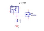
Look, I added such long time because I`m using simple chart to control the MOSFETs(IGBTs). I`m using un optocoupler and 12V power supply and 1k resistor. The problem is this resistor. If it`s smaller the voltage on it is not enough to open the transistor, but this big resistor sets the turn off time of the transistor to big value. So I was warried about not to destroy the transistors and added very big value for the dead time.
As i use my calculations I think I could drop down the dead time to around 100 or 200 us. I think this will be enough low. I think bead time should be 3 time shorter then the PWM pulse which is 500us.
I`ll be glad if you have any idea how to change my chart to use a smaller gate resistor.

chart.jpg
 

When I hear about 3 phase inverter, I think of a 3 phase bridge (double-H) and complementary control of high side and low side switches. With 2 kHz PWM frequency, dead times up to 10 or 20 us may be reasonable. I agree, that push-pull gate drivers will be required to achieve it.
 

With 2 kHz PWM frequency, dead times up to 10 or 20 us may be reasonable.
But look at this if we devided the period to 40 points(500us each), and the counter must count to 157 for 500us. So for example in point 40 when we switch munis to plus wave we have sin(40*2*3.14/40)*157=1. So we have only around 3us duty cicle. So the dead time is around 497 us or I miss something??? Even if the pulses are center-aligned the 1 impulse has around 80 us duty cicle....
In this case how to achieve 10 to 20us dead time???
 

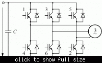
I'm asuming 3-phase-bridge, as said. Each motor terminal will be switched in push-pull mode by either activating high or low side switch. Dead time is the intervall where none of both is activated and should be generally short compared to the PWM period.

The below diagrams show the principle circuit of 3-phase bridge and sine PWM waveforms at a motor terminal and resulting difference voltage across a motor winding.


Status
Not open for further replies.

Similar threads

Part and Inventory Search

Welcome to EDABoard.com

Sponsor

Back
Top