Continue to Site

Welcome to EDAboard.com

Welcome to our site! EDAboard.com is an international Electronics Discussion Forum focused on EDA software, circuits, schematics, books, theory, papers, asic, pld, 8051, DSP, Network, RF, Analog Design, PCB, Service Manuals... and a whole lot more! To participate you need to register. Registration is free. Click here to register now.

Input impedance of a transistor at class C amplifier

Status
Not open for further replies.

goldsmith

Advanced Member level 6
Joined
Dec 14, 2010
Messages
3,981
Helped
741
Reputation
1,486
Reaction score
726
Trophy points
1,413
Location
Tehran - IRAN
Activity points
24,546
Hello Dear All
I know that how is the calculations of a class C amplifier . but i wondering , that how is the calculations of input impedance of transistor ( just transistor ) at class c amplifiers ?
Thanks in advance
Goldsmith
 

Hi Goldsmith,

what is the meaning of the term "impedance"? It is defined for sinusoidal signals only.
In this context - is the input current sinusoidal?
 

Hi Dear LvW
Thank you For your reply .
Yes My input is sine wave .

input impedance=input voltage/input current.

I have assumed that your input voltage is sinusoidal - but my question was if the CURRENT still is sinusoidal for class C operation.
If not - you cannot define any impedance.
 

Dear LvW
Thank you for your reply
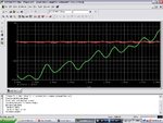
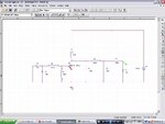
Here are my circuit and waveforms

Classc.JPG
classc2.JPG
( the Red waveform is the input current and it sinusoidal .)
Best Regards
Goldsmith
 

Goldsmith,

your diagram does not show typical class-C operation waveforms.
The reason: The operating frequency is approx. 100 MHz. Thus, parasitic influences play a considerable role but I doubt that this can be regarded as the "input impedance under normal operating conditions".
Question: Does the whole circuit operate (at 100 MHz) as a class-C amplifier?
 

Yes , it operated as 100MHZ amplifier as well as . ( i designed it for FM transmitter ). but when i want design the input matching circuit , i have some approximations for design . but i was wondering , that what is the input impedance , in fact ?

Respectfully
Goldsmith
 

Yes , it operated as 100MHZ amplifier as well as . ( i designed it for FM transmitter ). but when i want design the input matching circuit , i have some approximations for design . but i was wondering , that what is the input impedance , in fact ?
Respectfully
Goldsmith

At which point of the circuit did you measure the current as shown in your posting#5 ?
Correction: In which path did you.............
 

Thank you very much for your reply.
AT post #5 , you can see the circuit , that there is a red probe on the base . so the red prob is for red waveform.
Regards
Goldsmith
 

Goldsmith,

Try the following: Short the signal source and watch the output. I suppose you will see a signal. That means: Your amplifier oscillates!
 

AT post #5 , you can see the circuit , that there is a red probe on the base . so the red prob is for red waveform.

So you already have a value for the RF base input current.
If you also measure the RF voltage between base & GND, you could calculate a practical 100MHz "impedance" at the base -- even if voltage and current aren't 100% sinusoidal. Of course this "impedance" includes the impedance of the driving circuit, but that one can be back calculated, and so you can get an acceptable estimation for the (100 MHz) input impedance at the base.

But may be your simulator could directly output S parameter values?
 

Dear LvW
Again Hi
And thank you for your guide .
I did thing that you told me .
See below , please:

Without signal.JPG
Without signal circuitry.JPG

Respectfully
Goldsmith


And Dear Erikl
Hi
Thank you for your reply .
And thank you for your idea . i'll do it . and i think it will be interesting . but how can i do it with theorems?
And about : "But may be your simulator could directly output S parameter values?"
I know that what are the S parameters , but i don't know how can i use them and i'm completely confused by S parameters at these applications . but i love learn them .
Is it possible that you guide me please?
Best Regards
Goldsmith
 

Hi Goldsmith,

My recommendation: Before thinking about input impedance you should try to finalize the circuit. Is it really class-C ? Is the input-output behaviour as expected? What about self-oscillations (caused by idealized L and C)?
 

Dear LvW
Thank you for your help to me .
Yes It is a class C ,amp really , but what is your mean by that , accurately ? and it's behavior seems , not too bad but not very good that i want !
And about self oscillations , is it possible that you tell me more about them , and reason of them , please ?
With Appreciate and best regards
Goldsmith
 

Yes It is a class C ,amp really , but what is your mean by that , accurately ?

What is the characteristic of class-C operation (operational point)? Did you check?

and it's behavior seems , not too bad but not very good that i want !
And about self oscillations , is it possible that you tell me more about them , and reason of them , please ?


What about evaluation of your simulation in posting#12 ? For my opinion, this looks like a kind of self-excitement.
There is a lossless tank circuit at the input of the circuit (the transistor is off because of Vbe=0).
 

Dear LvW
Thank you for your reply . no i didn't check them , because , i don't , know , that what should be the specifications of a class C amplifier exactly .
And about self oscillating : i think the reason , is , that the transistor has leakage current , and this leakage current will go through the tank circuit . and thus it will try to convert it to a sine wave ( selecting it's desired harmonic) and so the amplitude of that oscillations is very low . am i right ?

Thank you very much.
Best Regards
Goldsmith
 

, i don't , know , that what should be the specifications of a class C amplifier exactly .

Goldsmith, are you joking?
Because in one of your earlier postings (posting #14) you did confirm : "Yes It is a class C ,amp really" (without knowing what it means?)
 

No No , sorry , i'm not joking ! i thought that here are the specifications that probably i don't know them .
Yes i know that what are the general specifications , ( the CE voltage waveform . the operation point . the collector current . THD , of out put signal , efficiency . and .... etc)
:smile:
i just thought , that if are any more specifications , i want learn them as some new things ( i know that you know that i know about class c amp , and i thought that with that question your mean was new things , that i can learn them from you )

Sincerely
Goldsmith
 
Last edited:

Dear LvW
Again Hi
So think your mean is that , why this arrangement hasn't any capacitor , in the collector in parallel with RFC , isn't it ?
Regards
Goldsmith
 
Last edited:

Hi Goldsmith,

no - my only concern consists of two questions formulated in posting #15 (stability and proper operation of the circuit).
If you are satisfied with the result - everything is OK. Are you?
 

Status
Not open for further replies.

Part and Inventory Search

Welcome to EDABoard.com

Sponsor

Back
Top