Continue to Site

Welcome to EDAboard.com

Welcome to our site! EDAboard.com is an international Electronics Discussion Forum focused on EDA software, circuits, schematics, books, theory, papers, asic, pld, 8051, DSP, Network, RF, Analog Design, PCB, Service Manuals... and a whole lot more! To participate you need to register. Registration is free. Click here to register now.

Help with RC timing circuit

Status
Not open for further replies.

holabr

Member level 2
Joined
Feb 12, 2010
Messages
46
Helped
1
Reputation
2
Reaction score
1
Trophy points
1,288
Location
USA
Activity points
1,719
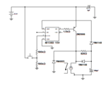
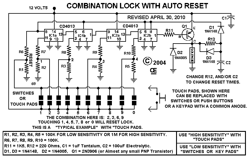
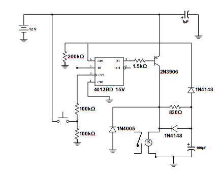
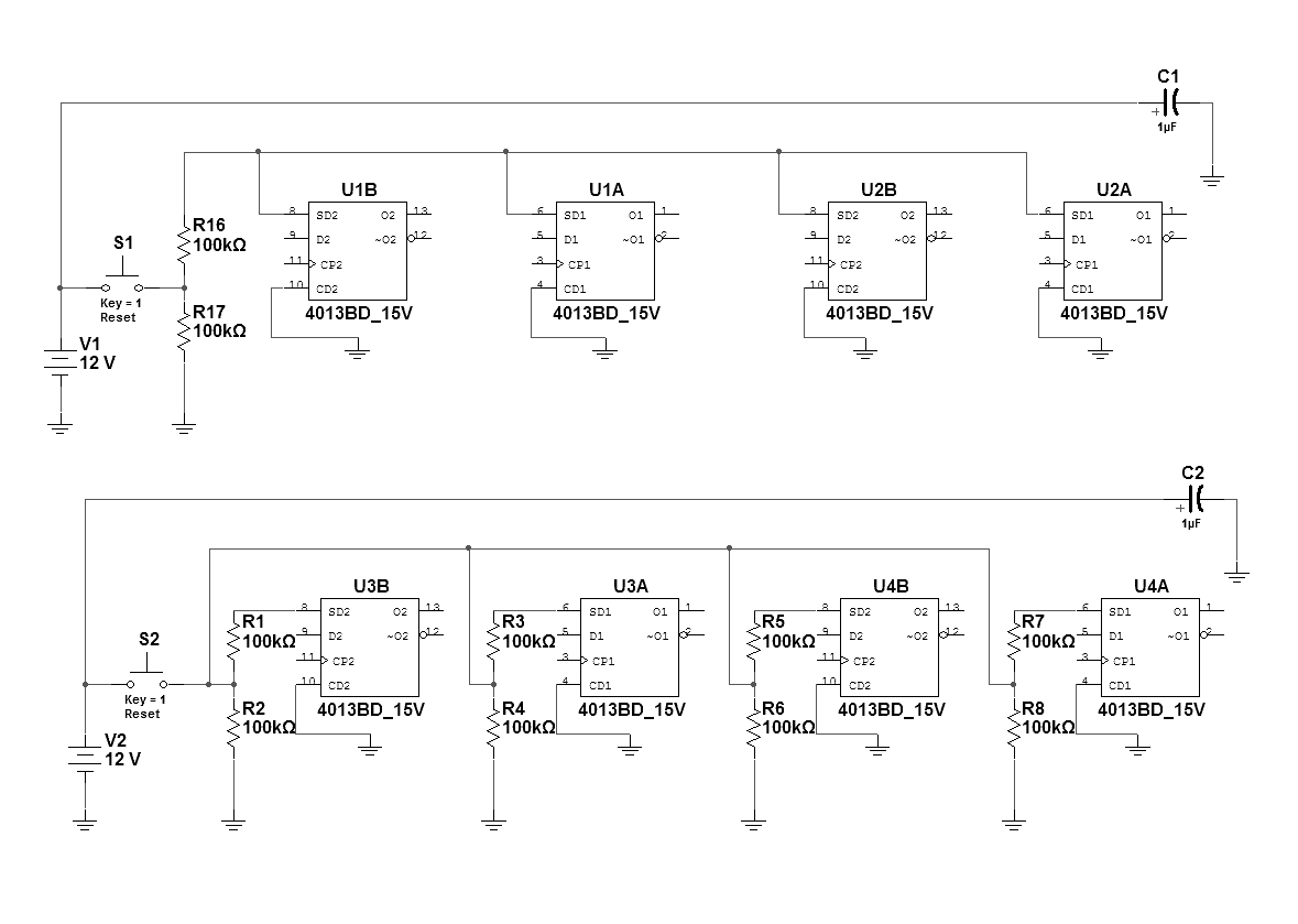
I'm working on a electronic combination circuit using a series of flip-flops. That last stage triggers a timing circuit that holds a relay closed for a set period of time. (I've attached a drawing of the circit below) Since I modeled this after some circuits I found on the internet and I'm pretty much a novice, I'm not sure exactly how this timing circuit works. I'd like to make the time that the relay stays closed adjustable with a pot but I'm not sure where the pot goes or what size it should be. Any help and guidance is appreciated.
 

Attachments

  • timer.png
    timer.png
    21.2 KB · Views: 119

That's an odd circuit. You should adjust the 820 ohm resistor to change the time.

I would say that this circuit is probably not reliable. Avoid it if possible.
 

I've tried adjusting the 820 ohm resistor in simulation but it doesn't seem to give me a very wide range for adjustment. Why do you think it is not reliable? I've attached the original schematic I used as a basis. What would you suggest instead? Can you point me to another schematic? This is going to be in an automotive application.


Your timing network will yield more 'on' time if you increase the 820 ohm resistor.

That resistor sends charging current to the 100uF capacitor.

When the cap reaches a sufficiently high volt level, the high signal goes to the 4013 IC inputs.

This changes their output state, and shuts off the PNP transistor. Turning off the solenoid.
 

Why do you think it is not reliable? I've attached the original schematic I used as a basis.

Spot the difference! Clue: a missing pull-down.
And bad ratio between divider resistors. You get either VDD/2 or 0V on inputs. VDD/2 is if I remember correctly an undefined level on inputs. I think the thresholds are 30% and 70% of VDD. Check the datasheet.
 
Last edited:

How's this? Does this eliminate the reliability issue?

Brad, should I also be able to decrease the "on" time by decreasing the size of the resistor? Is there a point at which increases and decreases no longer has a significant effect on the duration?
94_1329156288.png
 

Yes, and now I see I was wrong about the high and low levels from the button, sorry about that, I was too quick...

Maybe you should try to avoid resistors with such high values (200k and 100k) if your environment is damp.

The on-time is roughly proportional to R*C, in this case 820 ohm and 100uF.
One (possible) problem with the circuit is that it takes a long time to disharge the 100uF capacitor through the diode and the 200k resistor. This will block out pressing the button for several seconds. Maybe that's the intention...
 

It's an ingenious circuit, although tricky to get it operating right.

The resistor at pin 6 of the 4013 is a good idea, to make sure it will be pulled low initially.

should I also be able to decrease the "on" time by decreasing the size of the resistor? Is there a point at which increases and decreases no longer has a significant effect on the duration?

As post #8 mentions, the on-time is affected by the neighboring resistances around the capacitor. A 1000 ohm value for R12 might result in 1 second. A 10k might result in 10 seconds. Notice the capacitor is also discharging simultaneously through D3 and the solenoid.

Here are some direct tests to make.

Try putting a meter across the 100uF capacitor. You should be able to read the rising charge on it.

Also read the voltage at pin 6 of the 4013. You should see it rise as well.

The above tests are done while the relay is energized.

After the 2N3906 shuts off, the capacitor discharges. You can read how fast by using the meter.

The 1N4005 is there to absorb a high V spike coming from the solenoid at the instant it is shut off. At any time was the diode absent when the circuit was operated? If so then components could be damaged.
 
A follow-up question...

When resetting a series of flip-flops, does it make a difference if each has its own pull-down resistors (bottom circuit) or can they have them in common (top circuit)?
 

Status
Not open for further replies.

Part and Inventory Search

Welcome to EDABoard.com

Sponsor

Back
Top