Continue to Site

Welcome to EDAboard.com

Welcome to our site! EDAboard.com is an international Electronics Discussion Forum focused on EDA software, circuits, schematics, books, theory, papers, asic, pld, 8051, DSP, Network, RF, Analog Design, PCB, Service Manuals... and a whole lot more! To participate you need to register. Registration is free. Click here to register now.

Charge-pump Voltage Doubler

Status
Not open for further replies.

samiran_dam

Full Member level 2
Joined
Apr 17, 2010
Messages
122
Helped
3
Reputation
6
Reaction score
3
Trophy points
1,298
Activity points
2,419
Hi all,

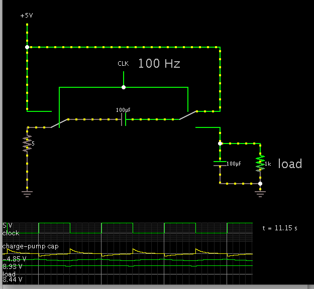
It would be very helpful if somebody review my explanation about the operation of this ideal voltage doubler based on charge pump shown in the following figure:

ideal_charge-pump_voltage_doubler.jpg

In Phase-1 (when Φ=1): S1 and S3 are closed and S1 is open - the capacitor is connected between the VDD and the ground.

The capacitor charges up to voltage VDD and the output (floating) is VDD

In Phase-1 (when Φ=0): S1 and S3 are open and S1 is closed - the capacitor's bottom plate is connected to VDD and top plate to the floating output node.

Initially output voltage is 2VDD as the voltage across the capacitor is VDD. But the capacitor will start charging up in the opposite direction so steady state value at output is 0. But it will be not observable in time-domain plot because there is no resistive path so the capacitor charges up to the opposite polarity instantaneously. If I connect a resistance (R) at the output node then it can be seen that the the output discharges from 2VDD to 0 with RC time-constant.

Am I correct? If not please explain.

Sam.
 
Last edited:

Hello Sam
At first time S1 and S3 are colsed and then the cap will charge up to vdd . and then at the second time , the s1 and s3 are open and s3 is closed and thus the voltage of vdd will sum with -vcap ( +v-(-v) =+2v)
Good luck
Goldsmith
 

Yes...I guess I was wrong...as the output node is floating, the capacitor will not charge in opposite polarity in second phase. But if I connect a resistor what will happen?
 

Your schematic is wrong but I think you have the right idea. The way it works is like this:

1. Capacitor is conected across the incoming supply.
2. Capacitor charges to incoming voltage.
3. Ground is connected (if it wasn't already) between incoming supply and outgoing ground line.
4. Capacitor is connected in SERIES with incoming supply and outgoing 'live' line.

So for example if you had 5V to start, you charge the capacitor to 5V then reconnect it 'on top' of the starting voltage so the new top has 10V on it.

Brian.
 

Dear Brian
Hello
I think the circuit is correct . see post #2 please.


and dear samiran_dam
my mean was not that the polarity will change . just the wire will change and you can test this circuit with some transient key and capacitor at pspice or the other simulators simply


Respectfully
Goldsmith
 

Dear Goldsmith,

Yes I will test...but right now I don't have access to the software.....once I go to lab I will check. But just for intuitive understanding - if I connect a resistance at the output node and suppose that resistance connects to the rest of the circuit in second phase then will the capacitor not be trying to get charged in opposite direction? And if so that will cause a drop of output voltage to 0 at steady state if we allow sufficient time in second phase (greater than 5/6 time constant (RC)). Am I correct?
 

The circuit is incomplete, as you need an additional switch at Vout connected to a reservoir cap to gnd.

Your problem is that you are thinking too much on voltages. For charge pumps, you work with charges!
At end of phase1, charge in cap is Q=C∆V=C(Vdd-0)
At phase2, charge in cap is Q=C∆V=C(Vout-Vdd)
Since no charging/discharging occurs in phase2, then the charge at phase2 must be equal to that at the end of phase 1!
 
I saw the same circuit samiran_dam posted which was followed by a more practical (if still ideal) circuit with a load resistance and capacitance:

chargepump.jpg

Vout was described as Vout = (C/(C+Cout))*2*Vdd which makes sense as the two capacitors are in series. What I don't get is why the Cout capacitance is necessary at all. Can anybody explain what would happen if Cout was removed? Thanks.
 

I learned how to create circuits in Falstad's animated simulator in the months since this thread began.

It's just the thing for helping us to conceptualize circuit action.

Screenshot of schematic in post #8 (as is, smoothing capacitor included), with scope traces:


What I don't get is why the Cout capacitance is necessary at all. Can anybody explain what would happen if Cout was removed?

Smoothing capacitor disconnected:


Schematic in post #1, as is:


Status
Not open for further replies.

Part and Inventory Search

Welcome to EDABoard.com

Sponsor

Back
Top