Continue to Site

Welcome to EDAboard.com

Welcome to our site! EDAboard.com is an international Electronics Discussion Forum focused on EDA software, circuits, schematics, books, theory, papers, asic, pld, 8051, DSP, Network, RF, Analog Design, PCB, Service Manuals... and a whole lot more! To participate you need to register. Registration is free. Click here to register now.

0 OHM resistor between +3.3V and GND

Status
Not open for further replies.

davidwuf

Junior Member level 1
Joined
Nov 9, 2011
Messages
18
Helped
0
Reputation
0
Reaction score
0
Trophy points
1,281
Activity points
1,418
Hi All,
Happy New Year!
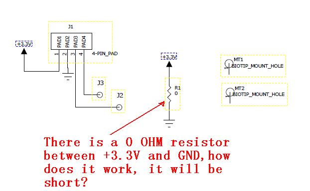
Please see the attached picture, there is a 0 OHM resistor between +3.3V and GND, how does it work, it will be short? anybody can explain how it work, thanks

Best Regards,
David Wuf

---------- Post added at 18:27 ---------- Previous post was at 18:26 ----------


Are you sure about the schematic?
Can it be a capacitor or the two ends being different than 3v3 and gnd?
 

Yes , Please see the pdf document attached.
 

Attachments

  • sch.pdf
    9.6 KB · Views: 104

What kind of device is it and what is the purpose of the external connections?
 

Even if it is a not fitted device, it is not good practice to do this, as if it gets fitted by accident you will have effectively about 0.003 ohms or less between power and ground, apply ohms lay and you ill get the current flow, about 1100A!!! Can I watch the first circuit switch on please:evil:
 

Hi,

That .003 or 0 ohm ohm resister is used as a dummy resistor. It is used to assign different net names. Finally we have to remove this resistor from the circuit.
 

Yes it possible.
this diagram does not show clearly that the negative side of the +3.3 v is connected to ground, we vjust assume it is so.
the designer can clearly attach the supply's (that maybe isolated ) + to ground and use - to feed the components, as can he use - the grd and use + to supply components, or chose not to join either to grd its just and option.
 

That's good schematic for a firecracker machine...
Can also be implemented with reverse soldered electrolytic super-capacitors.
 

Again, putting any sort of short or low resistance between what is clearly marked as a positive voltage and gnd is NOT good practice, full stop.
That .003 or 0 ohm ohm resister is used as a dummy resistor. It is used to assign different net names. Finally we have to remove this resistor from the circuit.
Why not miss the resistor out in the first place, then you still have different nets!!!
Everything about that part of the circuit is wrong, and bad practice and just asking for a major problem.
 

Maybe it was a capacitor. Maybe it was some other component. How did you deduce it is a 0 ohm resistor? In the real circuit, did you measure the resistance?

Could you post more details of the circuit? If you have the PCB, you could post the picture of the area around the 0 ohm resistor.

Usually 0 ohm resistors are used as jumpers. Maybe you made a mistake in tracing the schematic from PCB. Take a look again.
 

Status
Not open for further replies.

Part and Inventory Search

Welcome to EDABoard.com

Sponsor

Back
Top