Continue to Site

Welcome to EDAboard.com

Welcome to our site! EDAboard.com is an international Electronics Discussion Forum focused on EDA software, circuits, schematics, books, theory, papers, asic, pld, 8051, DSP, Network, RF, Analog Design, PCB, Service Manuals... and a whole lot more! To participate you need to register. Registration is free. Click here to register now.

0805 resistor argument needs referee

Status
Not open for further replies.

allenf

Member level 3
Joined
Jul 19, 2011
Messages
66
Helped
6
Reputation
12
Reaction score
6
Trophy points
1,288
Activity points
1,744
Ok guys heres one for you to solve.
BIG argument going on between me and the guy i`mdoing the schematics and layout for.
regulators are LM317`s
He has four PICS (2x8pin and 2x 18pin) the 8 pins drive the 1x 18 pin the other 18 pin is driven direct from regulator.
the other regulator is powering 8 pwm leds..
(so far??)

He reckons that on the TWO lm317s thathe is insistant that i use that i can get away with 0805 size chip resistors for r1 and r2 (the limit resistors)
I reckon that it would need at LEAST 1206 size to handlethe wattage,
he says I`m stupid and cant add up but the way i see it its simple math that is an 805 is 1/12 watt ( or 0.8) so 5 volts X (8x20mw) EXCEEDS the maximum of the 805..

Can somone please referee this one and say who is right who is wrong before we strangle each other.

Normally i would build it and proove a poin but 4 layers and a board house is gonna be pricey to proove a point IMO

Thanks in advance

Allen
 

I'm confused with the data you have provided, you wrote 5 volts X (8x20mw) , how does this volt multiplied with power work ?
What is the current through the resistor and what is the resistance value?
The typical 0805 is 1/10w but there are also higher ratings available, for example www.panasonic.com/industrial/components/pdf/AOA0000CE1.pdf 0805 is 1/8w

Alex
 

K these are 1/12 0805`s
5 volts X (8x20mw{LED runs at 20 mw 8 of them}) gives the wattage being pulled through the regulator
IE 24v input 5 volt output witha current of 0.5amp give 9.5 watts across the regulator ( thus the need for a heatsink there because that thing could fry eggs)
So on that fomula if i need to draw 8 x 20mw = 160mw then 12 volts in 5 volts out 12-5=7 7x0.16=1.12 watts across regulator exceeding the rating of 1/12 watt.
Or have I got my math wrong here and he is right
 

k lets make it easier


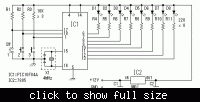
The leds are vishay tlcs5100 (50ma) so to run 8 of those (pwm`ed so only two are at full bright at any one time) is going to exceed the max for the 805 isnt it ?. As you see its drawn for 7805 but he is insistant that i use lm317`s NOT 7805`s
( would it be better to drive them straight off 12v with a 120r resistor to each rather than as drawn.
remember this is only a small part of the circuit requiring a regulator theres actually 4 regulators on the circuit
but these are the two causing arguments the one to drive the four pics I think may be ok and will conceed that 0805`s are ok but what do you think???
i spose i could use the 7805 and sort of scuff the label off it LOL
Cheers Allen
 

The power equation is P =V * I, this can be rewritten as
P = I² * R
or
P = V² / R

I have no idea what V * P is (5v * 0.16w as you say)

In order to calculate the consumption on the resistor you either need V (across the resistor) and I or V and R or I and R

So the resistor is 220 ohm and the current of the leds can be up to 50mA?

If the full brightness of the two leds that you mention is indeed 50mA (continuous) then the the resistor consumption is (0.05A)² * 220 ohm = 0.55w so the 0.1w resistor seems inappropriate.

Alex
 

The shown circuit (with a PIC driving the LEDs) neither allows 50 mA LED current nor 12V supply voltage for it. But that's not a problem of resistor rating. It's unclear however, which hypothetic design you're referring to.

The voltage divider of a LM317 (I won't name it limit resistors) doesn't require a high power rating. The datasheet suggests a resistor current of about 5 mA (R1 = 240) which would allow 0805 or even smaller for 5V as well as 12 V regulated output voltage.
 
I got carried away with the question instead of checking if the mentioned 50mA can be provided from the PIC output , I should have known better...

And I think FvM is right and you mean the two resistors of the LM317 so my previous answer seems irrelevant...
The resistor from output to ADJ has always 1.2v across it and is actually selected to have a current of a few mA (for 220 ohm the power is just 6mW) and the other resistor from the ADJ to gnd is also not a problem , the voltage across it is (Vout-1.2v).

Alex

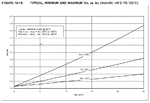
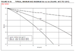
Below are the graphs that show the typical behaviour of PIC16 when you sink/source current

PIC16F_VOL-IOL.gif

PIC16F_VOH-IOH.gif
 
Last edited:

K thnx for that alex
I have to conceed I`m wrong.
I also overlooked the fact that the pic can actually only SOURCE a MAX of 100ma (being an soic I can basically knock that down to 70% as per microchips datasheets) so then yes he is right and an 805 is within limits
 

I also overlooked the fact that the pic can actually only SOURCE a MAX of 100ma (being an soic I can basically knock that down to 70% as per microchips datasheets) so then yes he is right and an 805 is within limits

Do you mean all the pins of the port as a total?
You said that you want 50mA from each pin (two active) and this is not possible as shown also in the graphs of the previous post, you can barely get 25mA with a high voltage drop and this is also the max mentioned in the datasheet.

pic16f84_electrical.gif
 

Both of u can be right
If u are using pwm means the leds are flickering and never totally on for more than say a minute , the small resistor will do.
more it also depends on the weather or surround temp .and u have a miscalculation .
if the resistors are for the leds u should do....v-v led+ actual voltage on resistor...5-1.5= 3.5 volts on resistor.
if pwm is is much lower cause u have to average.
good luck
 

Status
Not open for further replies.

Part and Inventory Search

Welcome to EDABoard.com

Sponsor

Back
Top