Continue to Site

Welcome to EDAboard.com

Welcome to our site! EDAboard.com is an international Electronics Discussion Forum focused on EDA software, circuits, schematics, books, theory, papers, asic, pld, 8051, DSP, Network, RF, Analog Design, PCB, Service Manuals... and a whole lot more! To participate you need to register. Registration is free. Click here to register now.

pic 16F877A is always burning when i used it in LIGHT TRACKER CAR

Status
Not open for further replies.

SLR722

Newbie level 4
Joined
Jan 30, 2012
Messages
6
Helped
0
Reputation
0
Reaction score
0
Trophy points
1,281
Activity points
1,328
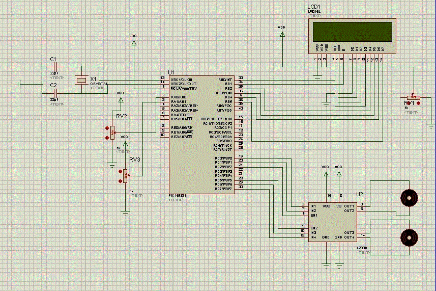
i made a light tracker car and i used pic 16F877A , L 293D (motor driver), DC motor , and LDR
but unfortunately i don't know why the micro controller is always burning after work in 3 mn
 
Last edited by a moderator:

Upload the schematic you have designed with PIC. Need to know the connections for better guidance.
 

Motors sometimes can produce spikes (very short duration high-voltages) in the power supply and this could result in resets or worse in damaged circuits. One solution it could be a separate power supply for the microcontroller and motors , install proper decoupling capacitors (better solution try a capacitor/inductor combination) for transient suppression in supply branch near to microprocessor and similar filter close to the power and ground of the L293D drivers.
Also you may need to add some recirculating diodes to the motor circuit to prevent problems when turning the motors off.
 

From your schematic all connections seem proper. I hope the power supply to both circuits (Microcontroller and L293 driver) are properly decoupled. If the motor produces any transient it will act on L293 first, as the motor is driven by the L293 not direct from supply circuit. Even then just for safety connect a 33Ω resistor in series with 1nF capacitor to the motor terminals. Though the bypass capacitors are integrated in the L293 output drives. Please check very carefully the Microcontroller's supply for any variation while the circuit is active.
Good Luck.
 

Though the bypass capacitors are integrated in the L293 output drives.

No "bypass capacitors" integrated in the L293D driver, just the flyback diodes (snubber diode) are internal in L293D. The voltage spikes can damage the semiconductor chips that control the driver in absence of decoupling capacitors and sharing the same power supply.
 

No "bypass capacitors" integrated in the L293D driver, just the flyback diodes (snubber diode) are internal in L293D.
Sorry for the typing mistake. Not CAPACITORS but DIODES.
 

Sorry for the typing mistake. Not CAPACITORS but DIODES.

THX too much ...
did u mean i can put 33Ω series with Diode for each output pins on L 293D .... or only used the diode without resistance .....???
 

Put 330 ohm resistors in series to outputs of microcontroller for safety. For example, in case input of motor driver ic is semi damaged and drawing excessive current or there is accidental shortage on board.
 
Last edited:

Put 330 ohm resistors in series to outputs of microcontroller for safety. For example, in case input of motor driver ic is semi damaged and drawing excessive current or there is accidental shortage on board.


what about diodes ....??? if i have to used it ... which pins input or output .....???
 

No "bypass capacitors" integrated in the L293D driver, just the flyback diodes (snubber diode) are internal in L293D. The voltage spikes can damage the semiconductor chips that control the driver in absence of decoupling capacitors and sharing the same power supply.
Put a resistor in series to +ve supply to microcontroller and put 5V zener diode and 104 capacitor between +ve and ground of microcontroller. Diodes are built in. Put .1uF( 104) capacitors on supply near every device
 

all devices shear in one power supply (6 V) ... did any problem for this ..... ???
 

This is the cause. Microcontroller needs 5V so if you put a resistor like 47 ohm in series with supply and 5V zener on microcontroller pins and bypass capacitors as earlier stated wiil solve the problem. Motor acts as generator, putting spikes on power lines.Now current will be limited and zener diode will regulate.
 

This is the cause. Microcontroller needs 5V so if you put a resistor like 47 ohm in series with supply and 5V zener on microcontroller pins and bypass capacitors as earlier stated wiil solve the problem. Motor acts as generator, putting spikes on power lines.Now current will be limited and zener diode will regulate.


the 2 DC motor will take all this voltage even to overcome initial condition
so i think the Voltage remaining is (2.5 -4v ) so the Microcontroller is working only for 3 mn otherwise the Microcontroller is burning quickly and never working
i believe the problem is with ic L 293 D motor driver ... but unfortunately i dont know what is it ....???
 

PIC runs at MAX of 5.5 volts so if you want to run 6 volts through it bang a 4148 diode in the v+ line the drop of 0.7 should takeyou down to the right leval.
BUT realisticly the better way IMO to do it is to run the motor at a slightly higher voltage (9v) the 298 drop of 3v takes you to 6 volts then run the pic through a7805 voltage reg to ensure you only get 5 volts at it.
Couple that with the decoupling caps and you have basicly a safe supply for your pic.
Personally I wouldnt run ANY analogue off the same +supply as a PIC due to the back emf and noise. even with diodes etc.

Good luck (lol I blewup loads of pics before i got it right)
Allen
 

When motor runs there are connections inside motor which make and break rapidly. If you measure voltage with voltmeter , it seems voltage is dropped but if you observe with oscilloscope, you can observe high voltage transients of back emf.This is same as spark coil works in your car generating thousands of volts from 12V car battery. You have to suppress these spikes.
 

quote above
"When motor runs there are connections inside motor which make and break rapidly. If you measure voltage with voltmeter , it seems voltage is dropped but if you observe with oscilloscope, you can observe high voltage transients of back emf.This is same as spark coil works in your car generating thousands of volts from 12V car battery. You have to suppress these spikes."

hence the use of a seperate supply regulator for the PIC
 

Status
Not open for further replies.

Part and Inventory Search

Welcome to EDABoard.com

Sponsor

Back
Top