Continue to Site

Welcome to EDAboard.com

Welcome to our site! EDAboard.com is an international Electronics Discussion Forum focused on EDA software, circuits, schematics, books, theory, papers, asic, pld, 8051, DSP, Network, RF, Analog Design, PCB, Service Manuals... and a whole lot more! To participate you need to register. Registration is free. Click here to register now.

How to cut off voltages greater than 5V using diodes?

Status
Not open for further replies.

scream_er

Member level 5
Joined
Feb 22, 2011
Messages
94
Helped
0
Reputation
0
Reaction score
0
Trophy points
1,286
Activity points
2,028
Hey guys,

I would like to know a simple way to cut-off any voltages greater than 5V before it goes into a micro-p ADC (its range is 0 to 5V). Will the attached configuration work?

diodes.png
 

Ok some problems here.
1) suppose just for example your amp output is 100v pp, u will pass a lot of neg current to grd.
2) u will destroy the 5v mpu supply and / or your amp.
3)if diodes short or open u have a problem either shorting your amp and or destroying your mpu.
4) checkout your mpu input resistance and that will tell u the serial (current limiting) resistors to must add to amp output to your diodes (use schottkey diodes) and diodes to mpu. if u are using more than 12v amp output you need to make a pi (3.14=pi)network ,2 regular 5.1v zener 4 resistors and 2 schottkey.
good luck.
 

Hey,
the amplifier gain set in such a way that it can output about 4.7V. But in the case if the voltage exceeds I want to cut it off. So can someone point me to a simple circuit for this.

Thanks
 

Your schematic in the first post is fine, you just need to add a resistor in series before the diode network so that if any of them conduct the current is limited.
You can use 1K or 4K7 but also check the max resistance that your ADC recommends, it is usually 10K so you have to keep the input resistance lower than that.

---------- Post added at 15:30 ---------- Previous post was at 15:27 ----------

I noticed that your diodes are not Schottky, you have to replace them becasue there are Schottky diodes inside the mcu so if you use normal diodes externally then they will never conduct because the internal ones will conduct first.

Check
www.cirrus.com/en/pubs/appNote/an20.pdf
 

@alexan_e: wht model of shottky diode would be appropriate? How will I know what model to take?

Thanks
 

Schottky diodes have a very low Vf (forward voltage drop) , typically about 0.3v compared to the 0.7v of a common diode.
When you connect a diode like in your schematic in the first post with the cathode connected in the 5v supply then in order for the diode to conduct you need 5v+0.7v=5.7v is you use a common diode or 5v+0.3v=2.3v which a Schottky one.
If you check the datasheet of you mcu it says that the max input is Vcc+0.3 (becasue there are internal diodes) so the 5v7 of the normal diodes will not do anyhting

If you check the link in the previous post you will see that it uses a BAT85 diode but there are many other models, depends on which ones are available in your area.
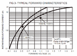
See this graph
1N5817_18_19.gif
see how low the diode starts conducting
 

@alexan_e: I have tried simulating the previous attached circuit. And according to simulation it cuts-off at 5.56V. So how can I make it lower to 5V, because my micro-p is going to burn otherwise :S
 

No your mcu is not going to burn at 5v , there are internal diodes and the input is limited to about 5.3v but the problem with the internal diodes is that they are very weak and that is why it is better to design this external protection.
Which mcu do you have, I'm sure that the datasheet mentions more than 5v from the inputs.

Which diodes did you use for simulation?
Did you add the resistor in the input?
 

I am using ATmega328 (which is in Arduino Uno). I used resistor value of in 10K series with the diodes. I used the 1N914 (as shown in the diagram, now gona try with BAT85 schottky diode).

---------- Post added at 22:29 ---------- Previous post was at 22:24 ----------

Just simulated with schottky BAT85 diodes. It cuts off at 5.25V. So, will this burn the ATmega328 microprocessor?

Thanks
 

When combining analog source with digital u need to be extra careful.
i do not know what that source is , and what is the supply voltage that source uses .
more what will happen to your expensive micro-p if the series transistor of the source fails.
tell me more of your source.

Hey,
the amplifier gain set in such a way that it can output about 4.7V. But in the case if the voltage exceeds I want to cut it off. So can someone point me to a simple circuit for this.

Thanks
 

I am using 9V source to supply the LM358 op-amps and I am using an electret microphone as input. So, basically I capture the voice from microphone and amplify it then connect the amplified signal to micro-p. So, incase if the output amplified voltage is greater than 5V I want to cut any voltage greater than 5V to safe guard the micro processors ADC.
 

The datasheet of your device says (in the electrical characteristics section)

Voltage on any Pin except RESET
with respect to Ground................................-0.5V to VCC+0.5V

so you may start having problems only if you go beyond -0.5v or 5.5v (using Vcc=5v)
 

So i guess if I use schottky BAT85 resistor I would be safe :) Thanks alot.
 

You can use many other alternatives, if you can't find the specific schlocky you can use many others , 1N5815 is another example
 

I tested with with a 6.2V zener diode to clip off the voltage. I connected the zener diode in the configuration as shown in the link (Zener Diode Tutorial) under "single zener diode clipping" and used a function generator to input a AC signal and an oscilloscope to see the ouput. The voltage was cut-off at 7.25V. So, my question is can I use a lower rated zener diode in the same configuration to cut-off voltage at 5V?

Thanks

---------- Post added at 04:00 ---------- Previous post was at 03:20 ----------

One more question is, what does the power rating of zener diodes indicate? Which power rating zene diode would be good enough for me? Will 500mW do?
 

No a zener diode is not a proper solution, the turn on corner of the is not sharp enough.
You just need to connect the two Schottky diodes to the power supply lines and you are done, this solution will work with any voltage supply level so if you have a 3v mcu then the diodes with conduct at -0.3 and +3.3 , if you are using 5v then -0.3v and 5.3v , there is no need to make any changes.

If you multiply the current that passes through the zener with the voltage across it you get the power consumption, this can't be more than 500mW.
I strongly recommend to avoid the zener for your application.
 

Hmm.. sure u using 9v only...(not +/- 9v) if so you will get a max 9vpp ac volts.
that means your sine wave has to pass a capacotor from amp output to pic a/d.
That means now u have a sine wave ranging from (+4.9 to -4.9) so no clipping needed.
Alexis is right u need to use fast scottkey zener diodes.

---------- Post added at 14:39 ---------- Previous post was at 14:37 ----------

Hmm.. sure u using 9v only...(not +/- 9v) if so you will get a max 9vpp ac volts.
that means your sine wave has to pass a capacotor from amp output to pic a/d.
That means now u have a sine wave ranging from (+4.9 to -4.9) so no clipping needed.
Alexis is right u need to use fast scottkey zener diodes.

---------- Post added at 14:40 ---------- Previous post was at 14:39 ----------

Hmm.. sure u using 9v only...(not +/- 9v) if so you will get a max 9vpp ac volts.
that means your sine wave has to pass a capacotor from amp output to pic a/d.
That means now u have a sine wave ranging from (+4.9 to -4.9) so no clipping needed.
Alexis is right u need to use fast scottkey zener diodes.
 

Status
Not open for further replies.

Similar threads

Part and Inventory Search

Welcome to EDABoard.com

Sponsor

Back
Top