Continue to Site

Welcome to EDAboard.com

Welcome to our site! EDAboard.com is an international Electronics Discussion Forum focused on EDA software, circuits, schematics, books, theory, papers, asic, pld, 8051, DSP, Network, RF, Analog Design, PCB, Service Manuals... and a whole lot more! To participate you need to register. Registration is free. Click here to register now.

classic integrator triangle wave generator--spikes on peaks of triangle wave

Status
Not open for further replies.

someWittyName

Newbie level 4
Joined
Jan 22, 2012
Messages
6
Helped
0
Reputation
0
Reaction score
0
Trophy points
1,281
Activity points
1,346
Hello all, first post. I'm fairly new to op-amps.

I've built a triangle wave generator using this design:
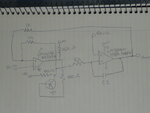
schematic.JPG

Nothing too fancy here. I'm running single supply off regulated 5V. I did add a external PNP transistor to my comparator's open collector output. I wanted a bit more current than it could handle. (I'm using a comparator here because I started laying out this circuit with a relaxation oscillator feeding an integrator, but I had NO feedback into the relaxation oscillator. This did not work out too well. :wink:)

C1 is .1uF and R1 varies, see included photos.

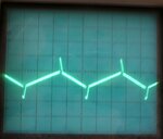
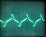
The issue I'm having is on the peaks of the triangle waves, there is a large spike in the direction the output was going.

R1 = 15K
15kR.JPG

R1 = 1K
1kr.JPG

R1 = 240
240R.JPG

And a picture of the bread board (just in case.)
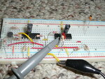
breadboard.JPG

So, these spikes are unexpected and unwanted. What are they caused by? What is this called and how do I go about solving it? (Have I introduced instabilities with such a large capacitance?)
 

Dear Friend
Hi
I think here is some problems:
1- probably , the slew rate of your op amp is not enough .
2- your design has some problem .
Do you know how is designing a simple single stage , miller integrator with op amp?
Read It's principles , please.
Best Wishes
Goldsmith
 

"So, these spikes are unexpected and unwanted. What are they caused by? What is this called and how do I go about solving it? (Have I introduced instabilities with such a large capacitance?)"

Kind of goes with the territory on those kinds of protoboards (high frequency circuit and fast rise-time edges).

There can be 5 to 10 pF of capacitance between each row of sockets and fast rise time edges (like from the output of the comparator) can couple to the integrator.

Obviously the 'charge' on the integrator cap did not change, as the output did return to the 'nominal' value after the spike occurred.

Could try feeding the comparator stage with a de-coupled DC supply (like a series 100 R to Vcc and cap like a ffim or ceramic .1 uF to ground near the comparator; electrolytic caps don't have good high frequency bypassing capability either).

Also, one could ground unused rows of sockets (pins) to act as shield between stages.

Jim
 

The waveform is only 5khz.
The triangle wave is 2 V, peak to peak. With the spikes, the whole signal is 5 V peak to peak. (R1 @ 1K.)
Interestingly, the spikes swing rail to rail.
The spike duration (10 us @ R1 1K) is too long to be noise from the comparator.
I've made sure that the outputs of the unused comparator and op-amps are not switching.
So, I don't think it's noise from somewhere.


In the datasheet for the op-amp, there is a VCO very similar to my circuit.
Also, there is this blurb:

To reduce the power supply drain, the amplifiers have a
class A output stage for small signal levels which converts to
class B in a large signal mode. This allows the amplifiers to
both source and sink large output currents. Therefore both
NPN and PNP external current boost transistors can be used
to extend the power capability of the basic amplifiers. The
output voltage needs to raise approximately 1 diode drop
above ground to bias the on-chip vertical PNP transistor for
output current sinking applications.
For ac applications, where the load is capacitively coupled to
the output of the amplifier, a resistor should be used, from
the output of the amplifier to ground to increase the class A
bias current and prevent crossover distortion.

I did connect a 1K resistor to ground from the op-amp output. This took care of the positive going spikes on the triangle wave, but not the negative going spikes.

I'm going to build my own external class A amplifier and see if that cleans it up.
I'll also try a new op-amp just incase mine is damaged.
Finally, I'll try removing the comparator, which has switching times in the hundreds of nanoseconds.
 

The spikes look like what happens when you apply AC square waves to a capacitor. It appears that while using it as an integrator, you're also introducing the effect of differentiation.

The website below shows the waveforms in animated fashion:

Differentiator

The website also has other circuits using op amps, called integrator and differentiator. They are similar, but not identical, to your schematic. They're worth a look too.

Integrator (inverting)

Differentiator (inverting)
 

Well, adding an external class B amp makes it look a lot like that o-scope picture where R1 = 240.


Looking at that website, I found this:
Triangle Wave Generator

Which is pretty much the circuit I've built. Square wave oscillator drives an integrator with feedback into the square wave oscillator.

I should say, I have built these style oscillators before, and without problem, they work quite well comparedt to a Wien Bridge style. Wien bridge oscillator - Wikipedia, the free encyclopedia

I did however, build it on perf-board (.1 inch centers/sea-of-pads board with top ground plane) and this was quite some time ago (probably in the 1990's).

The advantage of the comparator/square wave/integrator/Low pass filter type of oscillator is easy start-up, wide tuning range by varying a few simple parts and relatively constant amplitude.


Cheers.

Jim

Added:

The Linear Brief showing the "Easily Tuned Sine Wave Oscillators" circuit I once built (worked flawlessly BTW); today, I would substitute modern equivalent op-amp and comparator to what they show here:

**broken link removed**

(Note the date on the Brief; I prolly built a unit like this in the late 80's)
 
Last edited:

Referring to Post #1, when the PNP transistor changes its states (on/off), it introduces a sudden step current in R1 (as an increase or decrease). The spike at the opamp output is the relatively low speed response of the LM324 to this step current edge (though small). Obviously the effect of this step current at each transistion could be lowered by increasing R1.
 
Referring to Post #1, when the PNP transistor changes its states (on/off), it introduces a sudden step current in R1 (as an increase or decrease). The spike at the opamp output is the relatively low speed response of the LM324 to this step current edge (though small). Obviously the effect of this step current at each transistion could be lowered by increasing R1.
Yes, the first plausible explanation of the described effect. It's simply a feed forward effect due to the finite OP output resistance. Increasing the integrator impedance level by e.g. two orders of magnitude (50K instead of 500 ohm) will considerably reduce it, also using an OP with higher bandwidth.
 
That's interesting. Why does the op-amp swing to the rail if it's too slow for the input signal? One part of the op-amp internals is faster than other? Why am I not getting rounded tops on those triangle waves instead? Where should I start learing about these sorts of things?
 

Why does the op-amp swing to the rail if it's too slow for the input signal?
Feedforward leaves the slow OP in a passive role. The input current is simply overdriving the output.
 
  • Like
Reactions: KerimF

    KerimF

    Points: 2
    Helpful Answer Positive Rating
Where should I start learning about these sorts of things?

Learning about most special conditions as the one of this thread comes usually from experiments first as in your case (and mine as long I still work in new designs). Learning in depth (by formulas that include as possible all parasitic elements) of such unwanted responses may be needed if they cannot be avoided by a general understanding or we have no better components (devices) to choose from in order to minimize their effect.

For instance, the expression "OP in a passive role", mentioned by FvM, could mean that the linear characteristics of the opamp don't hold at each fast transition (input current in our case here). For example, at this moment its internal output impedance becomes relatively high (instead of a few ohms when linear).

If you will not find a reference talking about something you may notice in an experiment (hence true to you), you can always consider it (if it is important and you have time) as a personal project to analyse and study. And I won't be surprised if your work will be a good reference for others. I may say, no more than 30% of my knowledge in electronics came from reading other's works because the requirements I am asked for are usually special and my resources are limited. I mean if you really trust the intellectual power of your brain, you will surprise yourself :)

Kerim
 
  • Like
Reactions: FvM

    FvM

    Points: 2
    Helpful Answer Positive Rating
That's interesting. Why does the op-amp swing to the rail if it's too slow for the input signal? One part of the op-amp internals is faster than other? Why am I not getting rounded tops on those triangle waves instead? Where should I start learing about these sorts of things?

ALso, bear in mind from this point forward: do not place 100% faith in what your instruments show you, especially when dealing with fast risetime 'edges' on square-waves ... especially when using the plastic proto-boards which have inter-socket capacitances that are not seen on PCBs (printed circuit boards).

Always be aware of the top-end or 'maximum speed' your circuit devices may be capable of operating at, for they may be the source of oscillation and funny responses that simply looking at the schematic diagram does not suggest. Again, especially when using protoboards. Performing 'tests' of individual circuit components/sub-circuits (like op-amp separate from comparator) can shed some light on any anomalous behavior too ... always remember it is mother nature and physics that determine circuit operation, not how we 'think' these circuits 'should' operate. This is where good detective work and performing other tests works towards finding out ultimately what may be really place.


Jim
 

Status
Not open for further replies.

Similar threads

Part and Inventory Search

Welcome to EDABoard.com

Sponsor

Back
Top