Continue to Site

Welcome to EDAboard.com

Welcome to our site! EDAboard.com is an international Electronics Discussion Forum focused on EDA software, circuits, schematics, books, theory, papers, asic, pld, 8051, DSP, Network, RF, Analog Design, PCB, Service Manuals... and a whole lot more! To participate you need to register. Registration is free. Click here to register now.

Diode in series with Lead Acid (AGM) charger?

Status
Not open for further replies.

Half Awake

Newbie level 4
Joined
Jan 8, 2012
Messages
6
Helped
0
Reputation
0
Reaction score
0
Trophy points
1,281
Location
England
Activity points
1,347
Hello

I need a charger to charge 3 lead acid (AGM) batteries in series. I finally settled on this one through lack of choice despite it not having the connector I needed (it is simple enough to change). **broken link removed**

I measured its output voltages and it seems to be a bit higher than what is good for an AGM. This is something I have noticed as most battery manufacturers state voltages that should used to charge which are much lower than what the chargers supply. In this ones case it float charges at 13.9v. I know it is done because it makes them charge faster. I think this is a problem as AGM are more sensitive to being overvolted and can suffer as a result normally due to loss of surface area as bubbles building up on the plates through guassing (I think it is called). I would rather charge them at a slightly lower voltage. I don't mind waiting longer for it to charge.

Would it be advisable to place a diode in series with the 3 stage charger linked above to slightly lower its voltage without affecting its ability to function?

Also what is the name of the connector it uses, it looks a bit like an audio connection called RCA but it is bigger? I have searched for over an hour with no luck.

Thank you
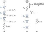
 

Yes, you can use diode to lower voltage. Each diode lower voltage by 0,7V.
Pay attention of diode current. Example P600M 6A case P6 price 0,1eur/piece.

When puting batteries in serie for charging pay attention on batteries condition, aging, internal resistance,...

This charger have 1,5A, you didnt say what batteries you intend to use, maybe you need to limit charging current to 0,7A or similar. See manufacturer data about battery charging current (You can give us battery product code and we will find it).

Connector is not problem. You can easely change or find adequate female/male connector. This from picture looks like audio chinch, you can always cut wire and put other connector.


Example of diode in serie :
images.jpg
 
Last edited:

Thank you for the fast reply. The batteries are currently in battery packs and I can not recall their exact types however if it is important I can open them up and take a peek. One pack contains 3 12v 12Ah in series the other contains 3 12v 7Ah in series. If my terminology is correct that is C/8 and c/4.6 for a 1.5A charger.

I also have some 6amp 100v Diodes sitting around somewhere which should do the job.
 

You should check data about batteries, because often charging current for 7Ah are 0,7A max 1-1,1A (with some conditions), of course some small batteries accept charging current to 2-2,1A (I recommend to see manufacturer data about batteries).
 

Thats it your charger (1,5A) corresponds to this batteries for charging
You can use charger with diodes to make lower voltage. :wink:


You should know that this charger what you show, probably will be very hot when charging, just to know.
 

I do suspect that when it is putting out 1.5amps for a few hours it would get quite warm (understatement). I will find out once I get the proper connector onto it.

I did originally consider opening the thing up in the hope that I could adjust the voltages using a preset resistor and maybe add a better heatsink but it is fully sealed. I could try opening it but would most likely need a hammer for that. I can't even add air vents in case I drill through something important.

If it does get seriously hot I could try adding a resistor in series or risk trying to break it open. :p To be honest I want to open it up more to see how it works than anything else.

Thank you for your help.
 

:smile: My friend I told You that small switchers can be very very hot. Of course their working temp maybe 70C-75C just to know.

If you open it be careful to protect yourself from electric shock, you can always put that into new case with some fans.


If you whant to open it use saw, and cut around on half, just trace where they use glue, about on half of case. There use saw and go around of case, and be carefully. Use periodically screwdriver.

Saw type is small fine for metal, not for wood. :wink:
 
Last edited:

" if it is important I can open them up and take a peek. "
very important if u can dismantle them and charge each separately its ideal .
aging batt. need separate charging or a good batt can be effected by a bad batt.
 

I am fully aware of you problem you are describing dselec, the batteries are in very regular use (often charged and discharged heavily several times a day) and are often under high current. Disassembling the pack every time just would not be practical.

In the past I have considered some kind of controller that can charge them in parallel and allow me to discharge them in series. Unfortunately I have yet to work out how to do this in a practical way.

If anyone has any ideas I would be glad to hear them.
 

Better is charging in serie from charging in parallel, but the same rules exists, internal resistange, battery aging,.....
When paralleling there is more problems then in serie.

All three batteries should be used as chain, never single, the same aging, and you can monitoring internal resistance happening and voltage when disharged and fully charged.
 

Status
Not open for further replies.

Similar threads

Part and Inventory Search

Welcome to EDABoard.com

Sponsor

Back
Top