Continue to Site

Welcome to EDAboard.com

Welcome to our site! EDAboard.com is an international Electronics Discussion Forum focused on EDA software, circuits, schematics, books, theory, papers, asic, pld, 8051, DSP, Network, RF, Analog Design, PCB, Service Manuals... and a whole lot more! To participate you need to register. Registration is free. Click here to register now.

Ferrite core for current sensing

Status
Not open for further replies.

Flavini

Newbie level 5
Joined
Jun 1, 2011
Messages
9
Helped
0
Reputation
0
Reaction score
0
Trophy points
1,281
Activity points
1,369
I am making a circuit for overcurrent protection where the circuit is shut off using a relay if current is greater than 10A. For current sensing, I chose to use a current transformer.
My question is that, if I'm measuring the current flowing through at 220VAC 50Hz, can I use a ferrite toroid? I was thinking of 1 turn and 100 turns. Will this work? Will there be a problem if I use ferrite at this low frequency?

Thanks.
 

Hello my friend
Yes you can use it simply , but at its secondary , you have to use an amplifier to increase the voltage , thus you can measure that agreeable , voltage , that is a linear function of your primary . ( your method , called , CT , measuring )
BTW , why , you didn't select Hall effect sensor ?
Best Wishes
Goldsmith

---------- Post added at 23:27 ---------- Previous post was at 23:26 ----------

BTW , you should use it as a series , coil with your AC current
 
Ferrite can work fine, but you have to make sure it has enough magnetizing inductance on the secondary to not load down the burden resistor, and that the secondary does not saturate. For low frequencies like 50/60Hz, laminated steel is generally a more convenient choice than ferrite.
 
Dear mtwieg
Hi
I agree with you , but i think that , he can use ferrite core with gap space . what do you think about this?
Respectfully
Goldsmith
 
A gapped core can be used, but it usually won't provide any benefit, since you'll have to make up for the decreased reluctance with more turns. Gapping a core only makes sense when its function is to store energy, and I've never seen a gapped CT (at least ones with burden resistors). The proper way to avoid saturation is to adjust the burden resistor and number of turns.
 
I was thinking of a small toroid with 1 turn, 100 turns and a 22 ohm load resistor. How accurate will it be? Will the voltage at the output of the current transformer (across the burden resistor) be linear? I want to use a ferrite core because it's cheap, easier to wind. Will there be any problem?

Hall effect sensor is too expensive.

How can I make sure that the secondary won't saturate?

What do you think?
 

When you are discussing actual dimensioning questions like burden resistor, you should consider the ferrite parameters in a first place (AL value, geometry, ferrite type).

As a rough estimation, for a medium size core (e.g. D=22 mm) and a usual power ferrite, you can expect AL of several 1000. This means, that 22 ohm would be considerably higher than the core reactance. As a consequence, the CT characteristic will be non-linear and temperature dependent. You would want a burden resistor which less than 1/10 of the reactance, better even lower. So the resistor should be clearly below 1 ohm. For the said assumed core size, 22 ohm / 100 turns would also result in core saturation.
 
Again Hi my friend
Because of that your current is AC i think you will not have any specific problem. by the way , you can use parallel ferrite cores ( use some of them in parallel with together , ) to be ensure that your ferrite can not be saturation . and if you use parallel cores , the ur will increase ( the inductance per one turn will increase , )
Best Wishes
Goldsmith
 

I don't know the exact AL of the toroid, but I think it's over 100.

So, if I use 50 turns and 0.1R resistor for sensing a max of 10A, how would that be? How would I determine how to avoid saturation?
To avoid saturation, would I increase or decrease the number of turns?
What if I were to introduce an air gap to decrease the AL?
 

I presume that you want design a current transformer. This means, that the magnetizing current should neglectable or at least small compared to the burden resistor current.

An AL value of 100 would be very low and means the core is nearly unusable for a regular current transformer. An AL number in this range can be expected for low permeability cores, that are used e.g. for filter chokes or RF applications.

An air gap has the same effect as a low core permeability and is unwanted for a CT as well.

Optimal number of turns mainly depends on the intended output processing method. One point is that even with a shorted secondary winding (e.g. by a C/V converter), the windings resistance will still cause a voltage drop and respective magnetizing current.
 
Right, if you're using a ferrite or powdered iron toroid core to measure 60Hz, you're probably gong to need a large number of secondary turns. That's why I recommend steel or iron, since it has very high permeability and Bsat, and low losses at low frequencies. Steel/iron toroids aren't common though. If you wan one then your best bet may be to dismantle a toroidal power transformer.

The basic math is:
Magnetizing inductance Lm= AL*N^2
Magnetizing impedance Zm=Lm*2*pi*f
You want Zm to be significantly higher than the burden resistance Rb. How much depends on your desired accuracy.

To avoid saturation, you should use a volt-time-product approach. But in general if you meet the above requirements then your likely to also avoid saturation (unless you expect to deal with very large currents).
 

you can make a cheap current sensor using ferrite but its not easy.
checkout this Power Meter Monitor

where using flyback cores.

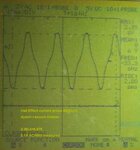
I had a go at it (not finished, might get back to it eventually)
here's the type of signal I was getting
_mg_9629.jpg

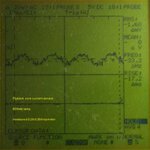
compare to what I can get from a halleffect sensor
HEprobe-vacuum.jpg

so anyway I hope you can see it is not exactly trivial to make use of the cheaper sensor way.

Using toroids is similar, I don't expect accuracy, but it is still a cheap way to sense current, quite ok
for setting some trigger level or the like.
 

Status
Not open for further replies.

Similar threads

Part and Inventory Search

Welcome to EDABoard.com

Sponsor

Back
Top