Continue to Site

Welcome to EDAboard.com

Welcome to our site! EDAboard.com is an international Electronics Discussion Forum focused on EDA software, circuits, schematics, books, theory, papers, asic, pld, 8051, DSP, Network, RF, Analog Design, PCB, Service Manuals... and a whole lot more! To participate you need to register. Registration is free. Click here to register now.

Microcontroller PC connection getting disconnected due to EMI

Status
Not open for further replies.

sabu31

Advanced Member level 1
Joined
Jan 28, 2011
Messages
446
Helped
12
Reputation
24
Reaction score
13
Trophy points
1,298
Activity points
5,153
Hi

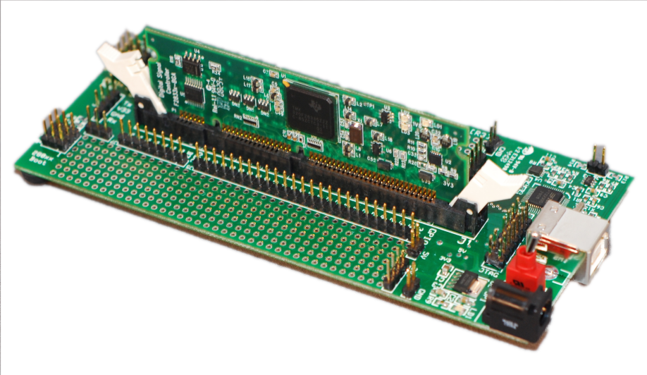
I am trying to control single phase inverter using TI Tms28335 microcontroller, using its development kit (control card and a docking station ) via code composer 3.3. However when the dc link voltage is increased to say 100V , the connection between the pc and microcontroller gets disconnected. TI people mentioned it was due to emi and i should pass the usb connection through ferrite core with few turns. I passed the usb through a torroidal ferrite core however ther was no effect. Is there any way to suppress emi (apart from layout ) as this is just prototype so final layout and system is not yet decided ,consequently lot of connecting wires is used for pwm,adc sensing etc.

Thankingyou
 

During test condition, this kind of EMI occurs frequently. It would be better if you can isolate the connection optically from PC RS232 To Your test board serial connections.
 

Try putting lots and lots of turns through the ferrite. Just to see if it works. If it doesn't then that means either there's another path for common mode signals in your system, or it's not a common mode noise problem. Can you describe how the inverter is interfaced to the MCU board, and what kind of load it's connected to? Is any other part of the system connected to earth ground?
 

Hi mtwieg.. I tried putting lots of turns on torroidal ferrite core and connected the two ends of wire with 100 ohm carbon resistor. No efffect as such. The Pwm output of the TMS28335 is given through an optocoupler (6n137) and a NOT gate to the mosfet driver IR2110. DC link voltage of the inverter is obtained through rectification(transformer isolated+diode rectifier+LC filter) of single phase ac . THe microcontroller board is connected to pc via USB cable (one which is used for connecting printers to pc). Actually I have not connected any connection to earth. Could that be the problem...
THank you.
 

Hi mtwieg.. I tried putting lots of turns on torroidal ferrite core and connected the two ends of wire with 100 ohm carbon resistor. No efffect as such. The Pwm output of the TMS28335 is given through an optocoupler (6n137) and a NOT gate to the mosfet driver IR2110. DC link voltage of the inverter is obtained through rectification(transformer isolated+diode rectifier+LC filter) of single phase ac . THe microcontroller board is connected to pc via USB cable (one which is used for connecting printers to pc).
Okay, so it sounds like you shouldn't have much trouble with ground loops if your MCU board is optoisolated from the inverter part. To clarify, which parts of the system are TI dev tools and which parts are your prototype (the H bridge? The gate drivers? The optoisolators?). Could you post some documentation for the docking station and/or the inverter? I'm wondering how its gate drive supplies are derived and if that's a clue to the problem...
Actually I have not connected any connection to earth. Could that be the problem...
THank you.
Probably not; if EMI is truly the issue, then grounding it probably won't help, but if you have optoisolators between the control and the inverter it might not hurt. You might try earthing the inverter just to see if it helps. Just verify that it is same to do so (it sounds like it should be, given your description, but you may be leaving something out... I've learned to be very careful when grounding power circuits, even when I think they might be isolated). If you don't want to connect it directly to earth, then connecting it to earth via a high frequency X capacitor can also work without as much risk.

Also another thing to possibly try is to change whether the shield of the USB cable is tied to the ground of the control board or not. I've often heard this is a culprit in EMI issues with USB.
 

Hi mtwieg, thanks for the reply.
which parts of the system are TI dev tools and which parts are your prototype (the H bridge? The gate drivers? The optoisolators?).
The prototype contains optocoupler(6n137), not gate (74Ls quad nand gate used to obtain nand gate), gate driver IR2110, . The inverter is simple full bridge inverter (mosfet IRFPE50PBF) and L-C filter. TI dev tools I have uploaded the image.
Also another thing to possibly try is to change whether the shield of the USB cable is tied to the ground of the control board or not. I've often heard this is a culprit in EMI issues with USB
How do i check this, I am sorry I didnt understand what is mean by shield.
Thanking you
 

Attachments

  • F28335 PGF controlCARD Schematic.pdf
    140.4 KB · Views: 86

Status
Not open for further replies.

Similar threads

Part and Inventory Search

Welcome to EDABoard.com

Sponsor

Back
Top