ian0mackenzie
Newbie level 2
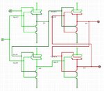
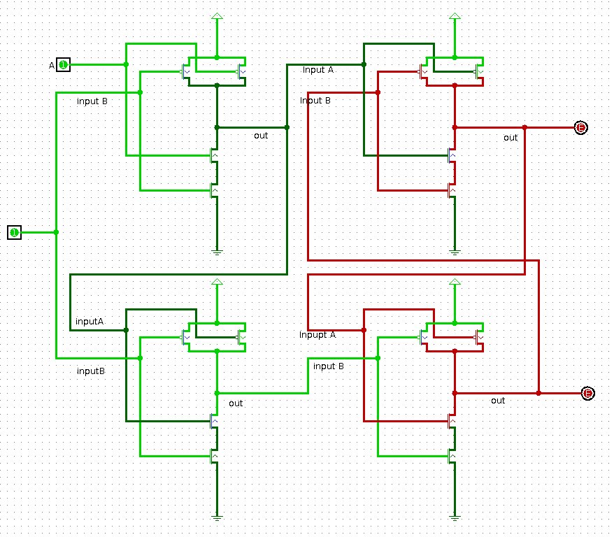
Hope this is the right place to post such a question... I've created some NAND gates in a program called logisim (google it - it's free!) and am trying to create a D-latch. The individual NAND gates work fine and give the correct output but - as you can see from the attached image - when everything is all hooked up the circuit isn't working. If anyone could take a look at the attachment and give their thoughts, or direct me somewhere better to ask the question, I'd appreciate it greatly!
The Image: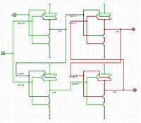
thanks!
The Image:
thanks!