Sajjadkhan
Full Member level 5
- Joined
- Sep 25, 2010
- Messages
- 307
- Helped
- 17
- Reputation
- 34
- Reaction score
- 16
- Trophy points
- 1,298
- Location
- Rawalpindi,Pakistan
- Activity points
- 4,199
high guys Its been a situation for me and i need your help to drive 3 Phase,180 HP, Delta connection water pump.
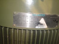
Specs:
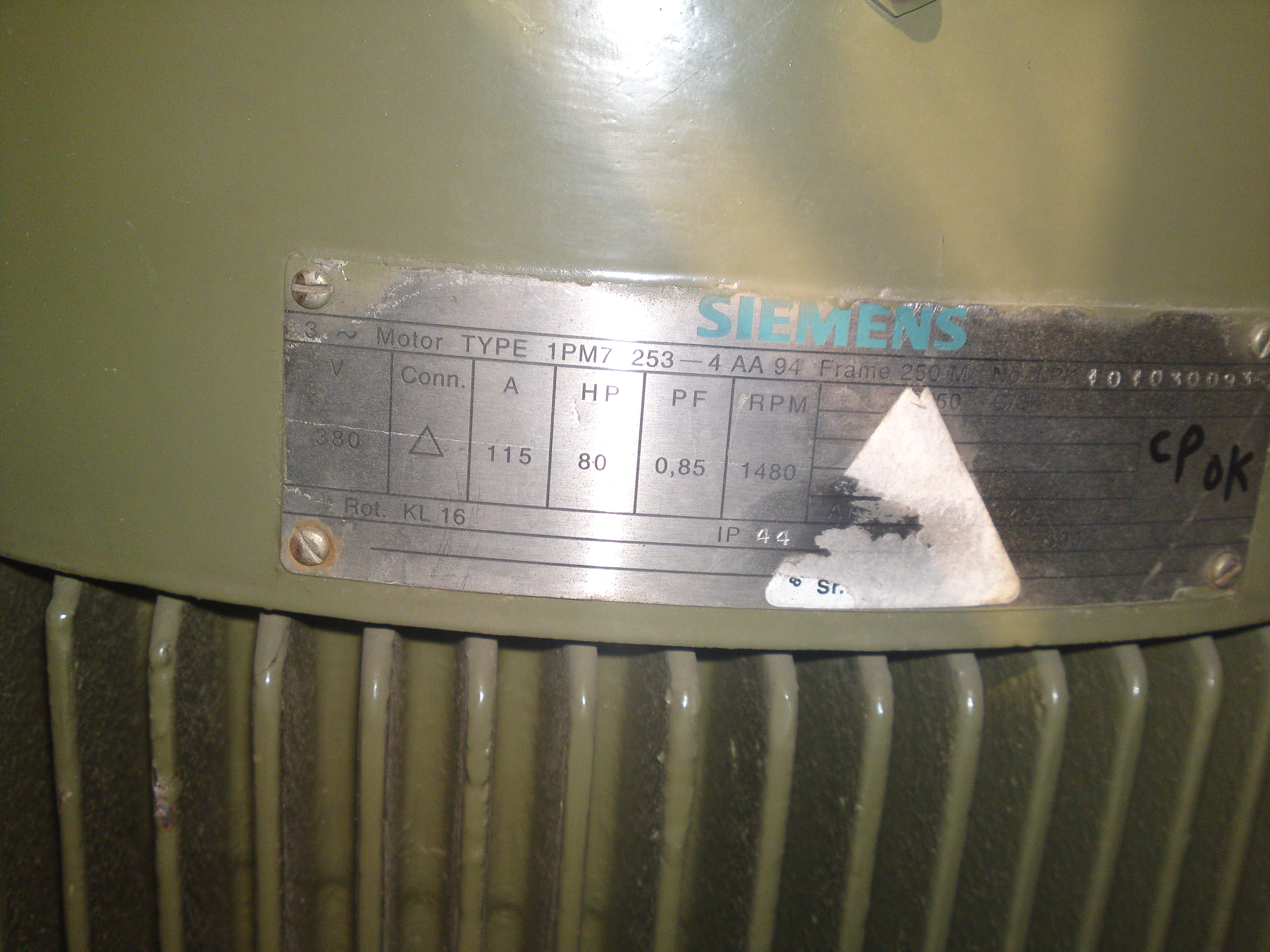
Voltage : 380
connection : Delta
Amps: 252.8
P.F : 0.85
HP : 180
Some questions about it:
1. I want to operate it via controller after sensing water level. I am dealing with this much of current my first time.What is best to operate it: high current relay or Solenoid switch?
2. Amps = 252 approx. Does this mean that 252 Amps is flowing through every phase? As it is 3 Phase, do i need relays/solenoid switch with 252 or above rating per phase or 252/3 Amps or above rating per phase?
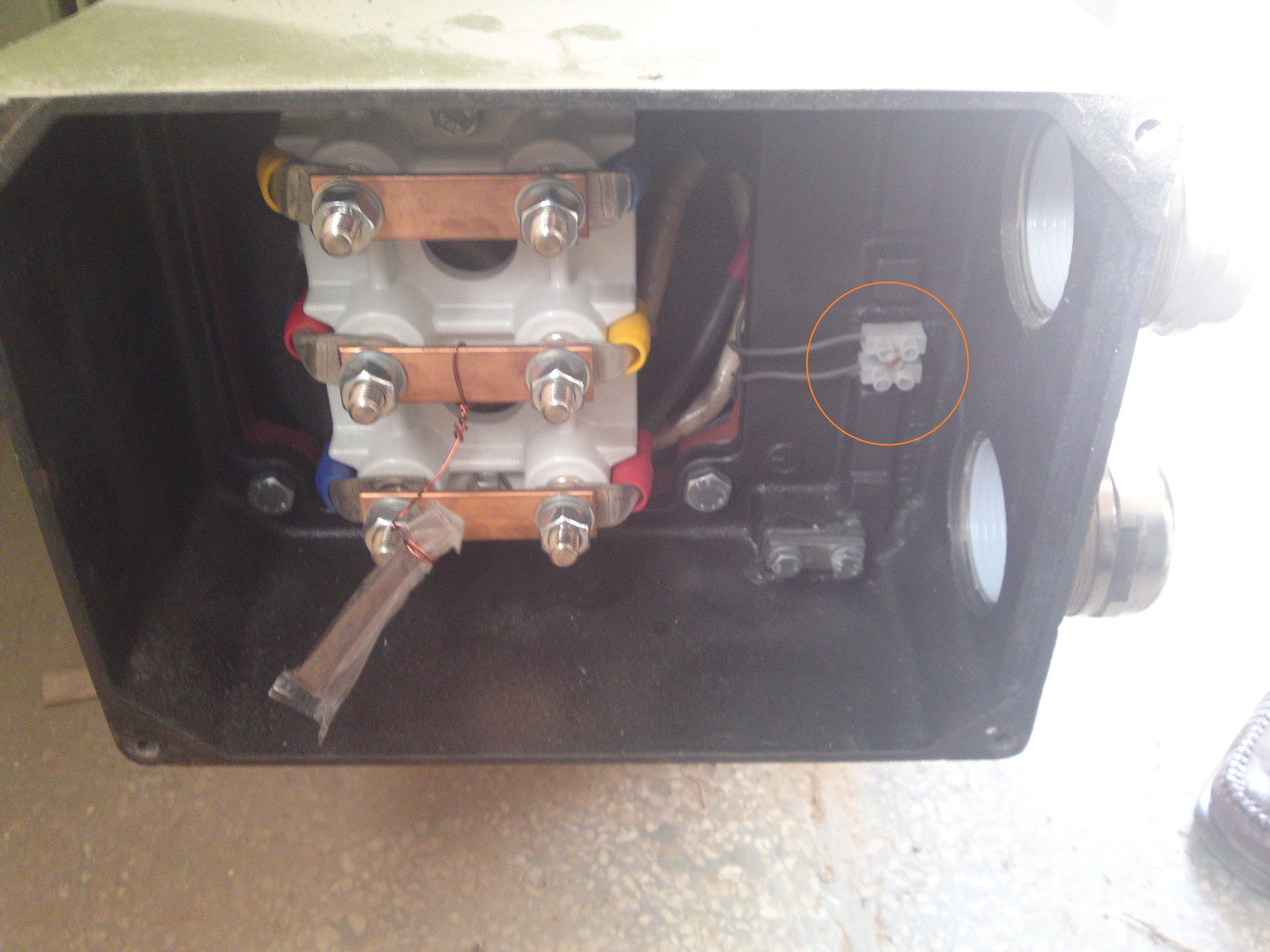
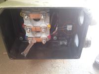
3. The wires in the connection box are of different colors representing different phases(i guess) so is it necessary to connect correct phase to correct motor terminal or should i connect randomly.
4. This one doesn't have a neutral right?
5. There are additional 2 wires connection in the box (Red Encircled) and i don't know what is it. i am thinking it as an RPM feedback, any thoughts?
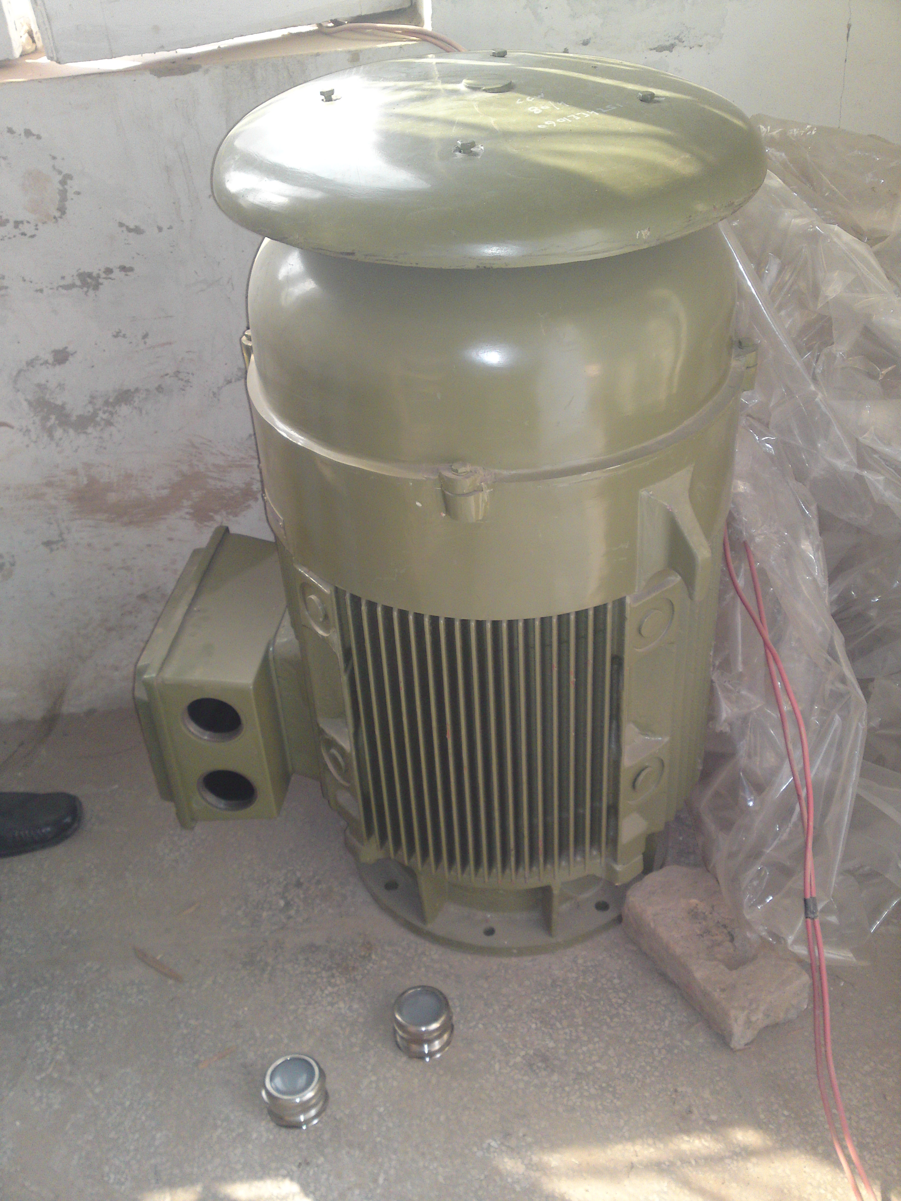
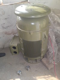
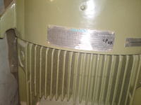
I am attaching some pictures below, its a 80HP water pump but 180 pump is exactly like that. It was packed so i couldn't get the picture.
Specs:
Voltage : 380
connection : Delta
Amps: 252.8
P.F : 0.85
HP : 180
Some questions about it:
1. I want to operate it via controller after sensing water level. I am dealing with this much of current my first time.What is best to operate it: high current relay or Solenoid switch?
2. Amps = 252 approx. Does this mean that 252 Amps is flowing through every phase? As it is 3 Phase, do i need relays/solenoid switch with 252 or above rating per phase or 252/3 Amps or above rating per phase?
3. The wires in the connection box are of different colors representing different phases(i guess) so is it necessary to connect correct phase to correct motor terminal or should i connect randomly.
4. This one doesn't have a neutral right?
5. There are additional 2 wires connection in the box (Red Encircled) and i don't know what is it. i am thinking it as an RPM feedback, any thoughts?
I am attaching some pictures below, its a 80HP water pump but 180 pump is exactly like that. It was packed so i couldn't get the picture.