Continue to Site

Welcome to EDAboard.com

Welcome to our site! EDAboard.com is an international Electronics Discussion Forum focused on EDA software, circuits, schematics, books, theory, papers, asic, pld, 8051, DSP, Network, RF, Analog Design, PCB, Service Manuals... and a whole lot more! To participate you need to register. Registration is free. Click here to register now.

AC controlled relay instead of current transformers

Status
Not open for further replies.

bobbybobby

Newbie level 3
Joined
Dec 27, 2011
Messages
4
Helped
0
Reputation
0
Reaction score
0
Trophy points
1,281
Activity points
1,330
Hello!

I want to add a mains socket to a vacuum cleaner so that when the device connected to it (a drill, sander, electric saw, whatever) is powered the vacuum cleaner also turns on. I googled a bit and read some about current transformers but wouldn't a simpler solution be to use an AC controlled relay? For instance something like this:

**broken link removed** (there are probably better candidates but this was the first one to turn up that seems to be able to be controlled by AC)

Connecting the relay coil in series with the external socket would close the relay and thus send current through it to the vacuum cleaner when a device is turned on.. this should at least work in theory I think? Any problems with this or are there better solutions? I want to avoid using a microcontroller for this project and I also want to keep it low budget.

Appreciate all answers!
 

Re: AC controlled relay?

The problem with this approach is that relays of this type have coil resistances of several thousand Ohms. The relay would actuate, but the voltage drop across the coil would be so high that the device (Drill, etc) connected in series with it would not operate. A current transformer is definitely the way to go for your application.
 
Re: AC controlled relay?

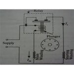
If you open a fridge compressor (AC motor) you'll find a small coil with thick copper wire and metal rod inside (usually placed into small plastic box near the motor connector). When you switch on the fridge the starting current of the motor pulls the rod and it pushes the contacts which temporary power on the start coil to mains. Once the motor spins with high speed the currents fall down and the realy switches off.

You can use such starting relay from fridge but you need to modify it slightly because the fridge motor starting current is > 10A so your device can't trigger the relay. You need to do both:
1. Decrease the strength of the returning spring
2. Add more turns on the coil. Because your currents are smaller you can use 1.0mm diameter wire and add as much tuns as you can.
 

Attachments

  • start coil.jpg
    start coil.jpg
    5.1 KB · Views: 146

Re: AC controlled relay?

Big thanks for the answers so far!

Unfortunately I don't have any extra fridges lying around. ;)

Let's see if I'm understanding this correctly... A "current transformer" is simply a normal toroidal transformer as far as I understand? It uses AC running through to wire in the hole to generate a lower voltage AC to the output pins, like 230V to 23V? I have a bunch of relays controlled with 5VDC capable of 10A. So I could use the CT which can output 5VAC and send that through a diode bridge in order to create DC. Then I can use a transistor to amplify the current enough (if it's necessary) to switch on the relay which powers the vacuum cleaner? Sounds like a simple enough solution.

Another question: can DC controlled relays be controlled with AC instead of DC? I have these kinds of relays at home: **broken link removed** I'm guessing not as it states "Coil rated voltage: 3-48VDC". But also, how does that fit the description of it being a 5VDC relay, can it also be controlled with anything up to 48VDC? If that's the case then I don't need to be so picky about the CT..

Sorry if I'm not making any sense, I'm just trying to understand it all.

edit: The types of relays I have are not sufficient for the high current I need, the datasheet states max power 800VAC/250W so I have to choose another type, however all my questions are still valid.
 
Last edited:

Re: AC controlled relay?

you can get spare fridge start relay for less tnan 10$, if you go into fridge repair facility you can get it for free. I think that such start relay (after modifications) is exactly what you need.

Current transformer could look as normal toroidal transformer. But current transformers have one important condition you need to fulfil - the loading resistance should be as low as possible (ideally 0 Ohm), i.e. you can't put directly on the current transformer output your relay. If you put it you could burn the current transformer.
 

Okay, would any of these do the trick:

**broken link removed**

**broken link removed**

I suppose the second one is easier to modify.

Hmm just found something else, what is this:

**broken link removed**
 

Unless I'm missing the point, wouldn't it be better to use a relay with an AC coil in Parallel with one device and use it's contacts to switch the power to the other.

I mean connect the relay coil across the supply to the drill (or whatever) so it energizes when it is turned on, then use the relay contacts to connect the power to the vaccum cleaner.

Brian.
 

The second relay
**broken link removed**
is ideal for modifications - you can add more turns on the coil and hence reduce the current for swithing on.

I don't know the characteristics of your loads but in my opinion it's achievable to reduce the start relay swithing-on current and get exactly what you need.
Of course what proposed betwixt - to connect standard relay in parallel to your load is a better idea if you have access to the place where the load is connected to the line.

The IMO - Finder Type Relay 230V 50Hz 60.32 is just a relay which could be powered directly from 220V so it's perfectly suitable for what proposed betwixt
 

Using an AC coil relay is intrinsically unsafe and home applications not very advisable if it can be avoided .
Preferable to use a laptop/mobile adaptor with ac mains input and 12VDC/16VDC /20V output .
Any relay with low voltage control coil is applicable .
Usable sources :: electronic Research /O E N /Goodsky /Leone /Omron /Parrys /Bulgin /can be used .
 

Why is a relay with an AC coil "intrinsically unsafe"?

They are standard components and usually certified by national safety labs. I use them all the time and know of many applications that use them quite safely. I can't recall ever seeing an AC relay causing a safety issue and I've been in the electronics business for over 40 years.

Brian.
I am in design of control panels ,,instruments , process and industrial controls for past 40yrs. Majority malfunctions and failures are insulation leakages on mains overshoots and over voltage from the supply.As such , it may not be advisable to go for such products in domestic applications ..Thus I had suggested application of low voltages circuits for domestic safety. vimal
 

Hi Vimal.

I understand your concerns and respect your experience. I have also seen failures due to insulation breakdown but mine have always been primary-secondary leakage or shorts in power supplies. I suppose the real moral of the story is never trust AC mains! I think it's up to bobbybobby to decide which route they risk.

Brian.
 

How about using an optoisolator instead? Here's a rough sketch I just made:

jmAol.png
 

The idea would work but there are some technical flaws. Firstly, you have the input to the opto-coupler wired wrongly, it would have to be across the AC lines to device 1 but after it's switch, secondly, the output (transistor side) can only handle a few mA and it would (try to) rectify the AC as well.

Using this idea, a better way would be to use a bridge rectifier across the AC side so both polarities are converted to one, feed this to the LED of an opto-triac via a resistor, then use the opto-triac to control a much bigger one controlling the supply to Device 2. The drawback to this is no isolation of one side of Device 2 supply and a relatively high leakage current through the triacs, especially as you would probably need a snubber as you have an inductive load.

Brian.
 

actually there are some opto couples with tyristor on the output side which can directly drive loads on the 220V line (<100mA). The load could be a relay with coil or some electronic relay which can amplify this current.

BTW, your schematic is not showing the shunting resistor - without it the whole current will flow through the opto diode and I would expect the diode will burn up.
 

Standard opto-coupled thyristors are peak current of 1Amp/230VAC.As such ,these are back to back LED driven thyristor which can be used only as aKi to gate drive with a limiting resister to the main BT136 used as drive thyristor for the vacuum cleaner motor having max. of 3to4 amp ratings .The BT136 is having ratings of 700v/6Amps .
Kindly see design accordingly
 

Status
Not open for further replies.

Similar threads

Part and Inventory Search

Welcome to EDABoard.com

Sponsor

Back
Top