dumborambo
Newbie level 5
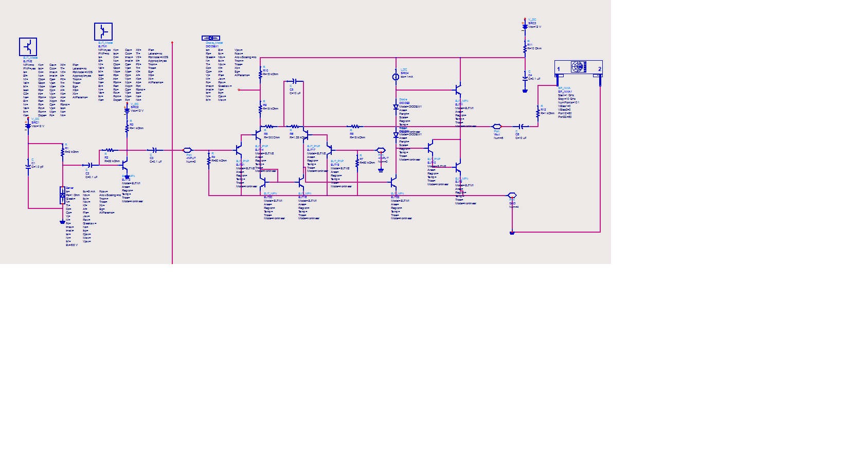
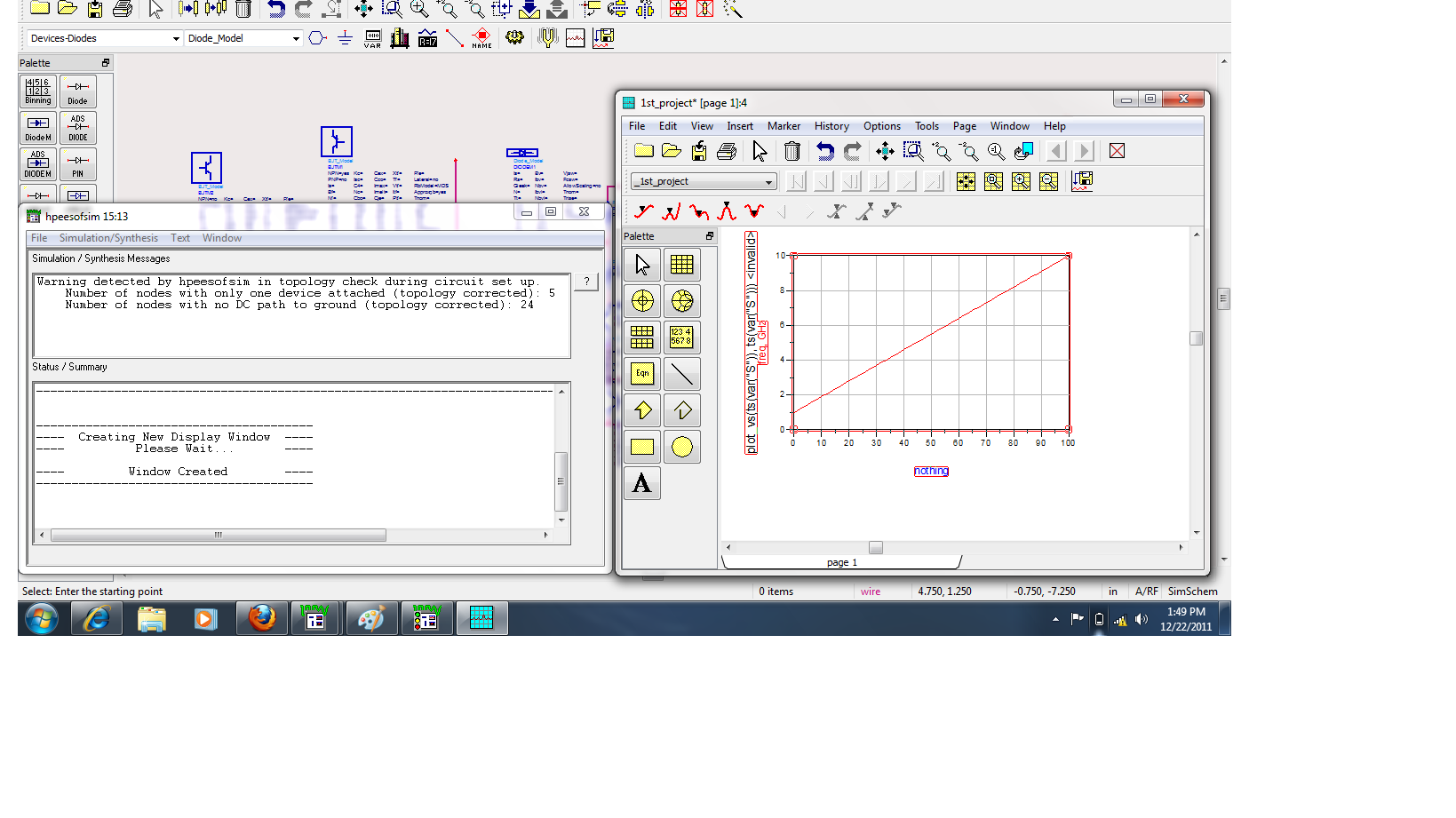
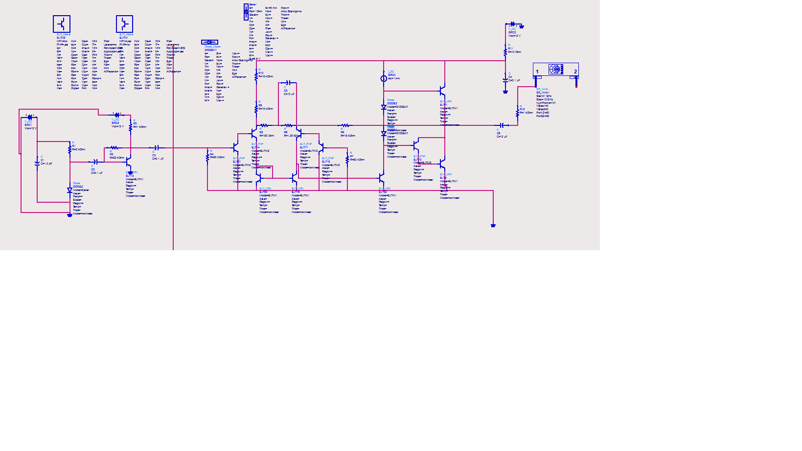
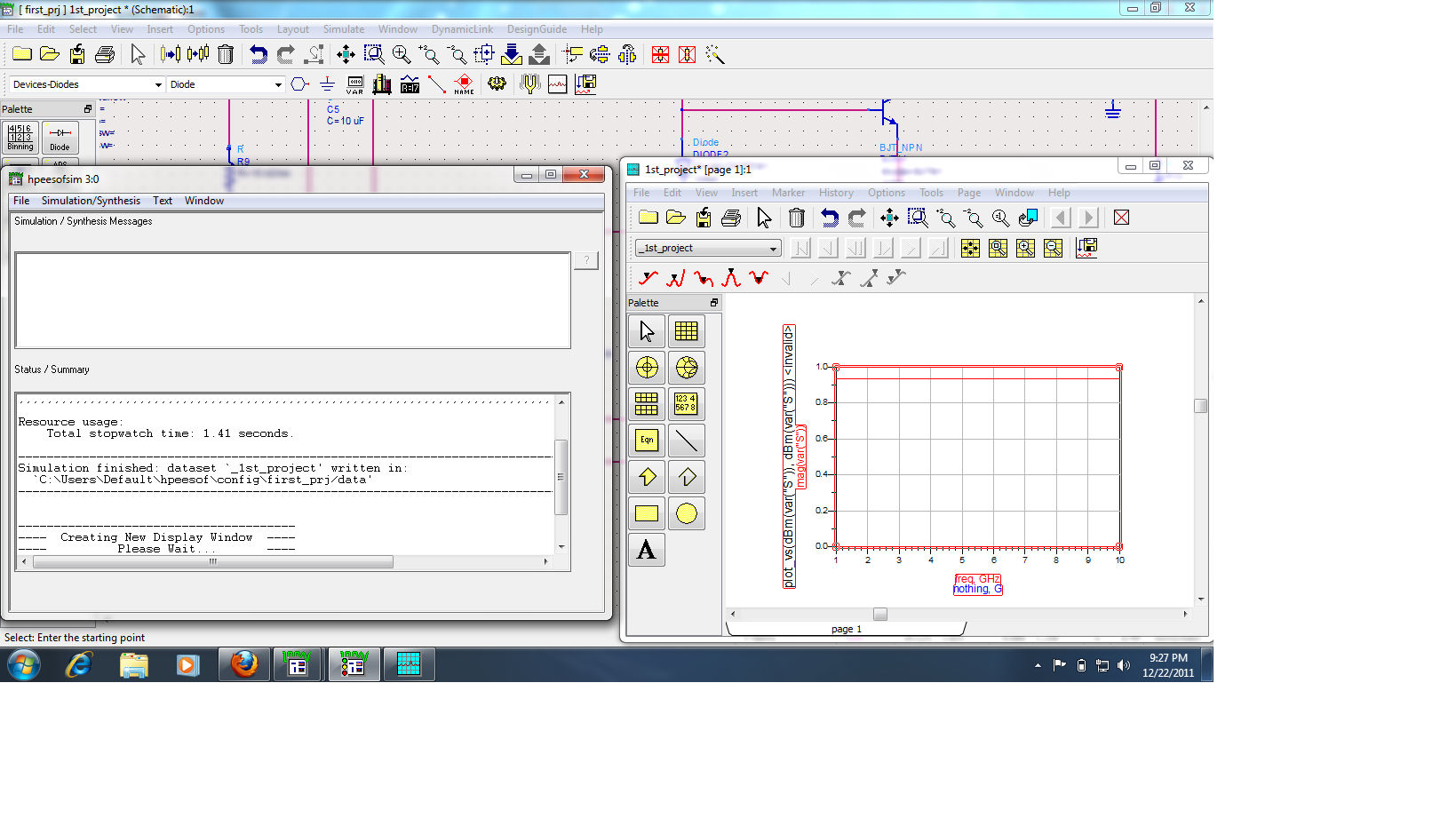
When I try to run this schematic it gives me the error that BJT1 is an instance of an undefined model BJTM1. And it gives error for every BJT that is in the circuit. How to solve this issue? Kind Regards

Follow along with the video below to see how to install our site as a web app on your home screen.
Note: This feature may not be available in some browsers.
Either include a model library containing BJTM1 or refer to any of the BJT models shipped with ADS.When I try to run this schematic it gives me the error that BJT1 is an instance of an undefined model BJTM1. And it gives error for every BJT that is in the circuit. How to solve this issue?