DeboraHarry
Full Member level 5
Help needed to understand HFSS ports - my simple model is wrong
I'm new to HFSS and find defining ports to be very difficult. In the example below, which consists of just one item (cylinder of dielectric) and a wave port, something is very wrong.
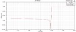
In this example, the model consists only of a cylinder of vacuum burried in a perfect electrical conductor. I've highlighted the port in the diamgram. Since this should act as a waveguide beyond cutoff at low frequencies, I would expect it to have a very poor return loss. Then as it starts to become a waveguide, I would expect it to have a poor return loss due to the fact that its shorted at the end.
What I'm seeing is a good return loss below about 9 GHz, then changing to poor above 10 GHz. I can't think of any logical explanation of why this would be so. Hence I've concluded my model is flawed. But this is about as simple as its possible to make any model - it only consists of one part.
Could some kind sole please take a look at this in HFSS, or could anyone explain why my reasoning is wrong.
I'm new to HFSS and find defining ports to be very difficult. In the example below, which consists of just one item (cylinder of dielectric) and a wave port, something is very wrong.
In this example, the model consists only of a cylinder of vacuum burried in a perfect electrical conductor. I've highlighted the port in the diamgram. Since this should act as a waveguide beyond cutoff at low frequencies, I would expect it to have a very poor return loss. Then as it starts to become a waveguide, I would expect it to have a poor return loss due to the fact that its shorted at the end.
What I'm seeing is a good return loss below about 9 GHz, then changing to poor above 10 GHz. I can't think of any logical explanation of why this would be so. Hence I've concluded my model is flawed. But this is about as simple as its possible to make any model - it only consists of one part.
Could some kind sole please take a look at this in HFSS, or could anyone explain why my reasoning is wrong.