Continue to Site

Welcome to EDAboard.com

Welcome to our site! EDAboard.com is an international Electronics Discussion Forum focused on EDA software, circuits, schematics, books, theory, papers, asic, pld, 8051, DSP, Network, RF, Analog Design, PCB, Service Manuals... and a whole lot more! To participate you need to register. Registration is free. Click here to register now.

question about common emitter amplifier with resistive emitter degeneration

Status
Not open for further replies.

jimito13

Advanced Member level 1
Joined
Nov 17, 2008
Messages
464
Helped
130
Reputation
262
Reaction score
113
Trophy points
1,323
Location
Greece
Activity points
4,929
Dear forum members and experts,

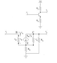
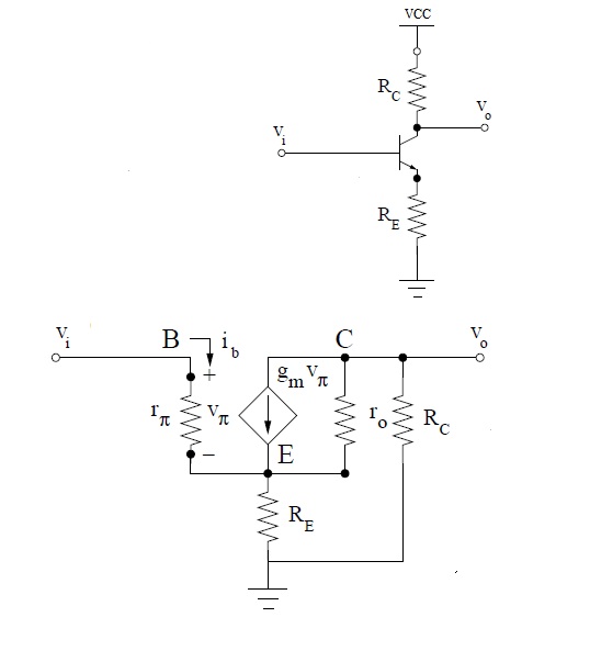
I have a very basic question concerning the small-signal analysis of a common emitter amplifier with resistive emitter degeneration.I provide the circuit's schematic and it's small-signal equivalent at the attached image :


My question is :

At emitter node of the above ckt we can write kirchoff's law : ie=ib + (gm*uπ)+ir0.Up to here everything is clear to me.
We know that ie=ib+ic but now we have one more current term that is the ir0,thus the equation ie=ib+ic=ib+βib=(β+1)ib=>ie=(β+1)ib is no more valid.Am i right or am i making a mistake in my thoughts?

Thanks in advance for any helpful answer.

Best Regards,
Jimito13-Analog RFIC Designer
 

Look at the equivalent circuit diagram and you will see that the current ic (current through the C node) now consists of two parts which are summed together.
That's all. The equation ie=ib+ic is always valid since it is defined for the currents through the nodes/pins E, B and C.

---------- Post added at 13:09 ---------- Previous post was at 13:08 ----------

 
Ok LvW,thanks a lot,i got it ;-)

Sorry to ask again...I have one more supplemental question :

I agree that the equation ie=ib+ic is always valid,but...i will pose my doubt below :

Now that ic has two parts (gm*uπ , ir0) we write the kirchoff's law at the emitter node (as i wrote it at my first post) as :

ie=ib+ic=> ie=ib + (gm*uπ)+ir0

How can we claim/prove that the equation with bold letters ie=ib+ic=ib+βib=(β+1)ib=>ie=(β+1)ib is still valid since it is proved given that
ic is equal β*ib and has no other parts?
 
Last edited:

Anybody willing to give a clarification to my question?
 

Ok LvW,thanks a lot,i got it ;-)

Sorry to ask again...I have one more supplemental question :

I agree that the equation ie=ib+ic is always valid,but...i will pose my doubt below :

Now that ic has two parts (gm*uπ , ir0) we write the kirchoff's law at the emitter node (as i wrote it at my first post) as :

ie=ib+ic=> ie=ib + (gm*uπ)+ir0

How can we claim/prove that the equation with bold letters ie=ib+ic=ib+βib=(β+1)ib=>ie=(β+1)ib is still valid since it is proved given that
ic is equal β*ib and has no other parts?

Therefore, β = [(gm*uπ)+ir0] / ib :wink:
 

Therefore, β = [(gm*uπ)+ir0] / ib

Yes but we also have : gm*uπ=β*ib , thus ir0=0!

I know that i have a misunderstanding above and i am waiting for a clear answer,not just an equation with no explanations...
 

Yes but we also have : gm*uπ=β*ib , thus ir0=0!

I know that i have a misunderstanding above and i am waiting for a clear answer,not just an equation with no explanations...

Hi Jimito,

you should know that the common equation ic=β*ib is a simplification only.
It results from one of the twoport equations describing the BJT in hybrid form (h-parameter) :

i2=h21*i1+h22*v2

In common emitter configuration: i2=ic ; i1=ib and v2=vce

From this: For v2=0: ic=h21*ib=β*ib (h21=β).

Because of the condition v2=0 the current gain h21=β is called "short circuit current gain".
That's the secret of the contradiction you might have seen.

---------- Post added at 14:01 ---------- Previous post was at 13:57 ----------

One additional remark:

The parameter h22 (output conductance) is a measure of the slope of the Ic-Vce characteristics.
Thus 1/h22=ro.
 
Last edited:
Hi LvW,

I can understand your analysis absolutely but the question still remains in my head...If this doesn't bother or take time i would like to ask you for further assistance :

For the ckt i uploaded how can i write the equation ic=β*ib in a correct way?And what ic is the one that fits this equation?I suppose from the above that the correct equation is : ic=β*ib => (gm*uπ)+ir0=β*ib .But now if we take this equation as correct then gm*uπ≠β*ib => uπ/ib ≠ β/gm => rπ ≠ β/gm !!!

Thank you in advance for any helpful answer.

Best Regards,
Jimito 13-Analog RFIC Designer
 

Jimito, Hello again !

Sorry, but I don't understand your question "For the ckt i uploaded how can i write the equation ic=β*ib in a correct way?"

As I have tried to explain: This equation is NOT correct within an amplifier circuit - and, therefore, you cannot write it in a "correct way".
It is a simplified equation that is correct only for the case Vce=0 (ac wise only).

---------- Post added at 16:16 ---------- Previous post was at 16:14 ----------

Another view: The simplified approach cannot be correct by 100% since the BJT is not an ideal current source.
 
Allright,but can somebody explain to me why in all books when they subsitute a circuit with BJT devices to it's small-signal low-frequency equivalent they write next to the voltage contolled current source either gm*uπ or β*ib (implying that those quantities are equivalent)?

If the equation gm*uπ=β*ib is NOT valid in a practical circuit then the equation that we all know rπ=β/gm is NOT valid as well!
 

Correct! It is "not valid".
However, don't be to disappointed - nothing in the electronic world is correct by 100%.
Because of other uncertainties (in case of transistors: very large tolerances) it is a good engineering practice always to neglect some minor influences.
This leads to equations that are handy and exact enough for most purposes.

For the particular case under discussion:

vbe=h11*ib + h12*vce
ic=h21*ib + h22*vce

That means: transconductance g=ic/vbe=(h21*ib + h22*vce)/(h11*ib + h12*vce)

Simplification: For vce=0 (neglecting backward influence and output conductance): g=h21/h11=β/rbe
 
Jimito, perhaps the following remark can help:

If the equivalent small-signal circuit contains a cuurent source i=ib*h21 or i=g*Vbe the simplification that I have mentioned very often is corrected by additional elements which represent the neglected terms:
ro=1/h22 in parallel to the current source and
v12=h12*vce in series with h11=rbe .
 
Allright,but can somebody explain to me why in all books when they subsitute a circuit with BJT devices to it's small-signal low-frequency equivalent they write next to the voltage contolled current source either gm*uπ or β*ib (implying that those quantities are equivalent)?

If the equation gm*uπ=β*ib is NOT valid in a practical circuit then the equation that we all know rπ=β/gm is NOT valid as well!

most books all assume ro is very high and hence iro is negligible.
 

Ok guys i run through the theory and the equations as LvW guided me and now things are clarified to me.Thanks a lot for your help.
 

Status
Not open for further replies.

Part and Inventory Search

Welcome to EDABoard.com

Sponsor

Back
Top