EwanC
Newbie level 1
- Joined
- Dec 4, 2011
- Messages
- 1
- Helped
- 0
- Reputation
- 0
- Reaction score
- 0
- Trophy points
- 1,281
- Location
- Christchurch, New Zealand
- Activity points
- 1,295
Hi all,
I'm currently designing a device which will run from an automotive 24V battery on a running vehicle (up to 29V when charging). The device will include a UHF radio module (0.5W Tx power), a microcontroller, a reed switch and a few LEDs. The radio and microcontroller run on 5V. Usually I would use a simple LM7805-type linear regulator for a device like this, but in this case it is impractical due to the large heat generated across the regulator when the radio is transmitting (~0.5A load current when transmitting = ~13W across linear regulator). I'm much more comfortable writing embedded software than designing analogue electronics, so thought I'd post on here in the hope someone would point out my stuff ups in the buck regulator design :roll:.
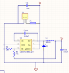
I've designed a buck regulator based on the LM2842X controller, using **broken link removed** and using the guide at **broken link removed**. I've tried to ensure the regulator always operates in continuous conduction mode - looks more difficult to make a robust regulator which operates in discontinuous mode. Since the minimum load current is rather low (~25mA, for a 'power on' LED, the microcontroller and the standby current draw of the radio), I've had to use a high frequency controller (550kHz switching) and a large inductor (220uH). I arrived at the figure of 220uH by setting the inductor ripple current to 40mA (then the ripple amplitude is 20mA, and the inductor current will never fall to zero) and using the formula
\[L = \frac{({V}_{in}-{V}_{out})*{V}_{out}}{{V}_{in}*{I}_{ripple}*{f}_{sw}}\],
from the LM2842 datasheet, with Vin = 35V for an extra margin. I've selected a **broken link removed** inductor - this has a DC resistance of ~0.35Ω and saturation current rating over 2A. Is this a suitable inductor value and part to use?
I've chosen a 100uF ceramic capacitor (TDK C3225X5R0J107M) as the output capacitor. I reached this value by using Eq. 3 of the 'Buck-Converter Design Demystified' page (linked above) for an output voltage ripple of 100mV. My concern with this part is that its very low ESR (3.5mΩ at 550kHz) may cause the controller to become unstable. The LM2842 datasheet says the output capacitor should have an ESR of 0.1Ω or less, but does not mention stability. I've seen datasheets for other buck regulator controllers state a minimum output capacitor ESR requirement for stability. Is it safe to assume I can use an ESR as low as I like, since it's not mentioned in the datasheet? Or should I try to find a part with a higher ESR?
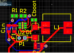
Finally, I've posted a screenshot of my current PCB layout. This is a two layer board, with the ground pours on top/bottom removed in order to make it easier to view. I've tried to follow the layout information in the datasheet and in the National Semiconductor application note about SMPS layout (AN-1149). Could someone have a quick look at it and perhaps offer tips on how to make it better?
Many thanks,
Ewan Coldicott
Computer Engineering student, University of Canterbury
I'm currently designing a device which will run from an automotive 24V battery on a running vehicle (up to 29V when charging). The device will include a UHF radio module (0.5W Tx power), a microcontroller, a reed switch and a few LEDs. The radio and microcontroller run on 5V. Usually I would use a simple LM7805-type linear regulator for a device like this, but in this case it is impractical due to the large heat generated across the regulator when the radio is transmitting (~0.5A load current when transmitting = ~13W across linear regulator). I'm much more comfortable writing embedded software than designing analogue electronics, so thought I'd post on here in the hope someone would point out my stuff ups in the buck regulator design :roll:.
I've designed a buck regulator based on the LM2842X controller, using **broken link removed** and using the guide at **broken link removed**. I've tried to ensure the regulator always operates in continuous conduction mode - looks more difficult to make a robust regulator which operates in discontinuous mode. Since the minimum load current is rather low (~25mA, for a 'power on' LED, the microcontroller and the standby current draw of the radio), I've had to use a high frequency controller (550kHz switching) and a large inductor (220uH). I arrived at the figure of 220uH by setting the inductor ripple current to 40mA (then the ripple amplitude is 20mA, and the inductor current will never fall to zero) and using the formula
\[L = \frac{({V}_{in}-{V}_{out})*{V}_{out}}{{V}_{in}*{I}_{ripple}*{f}_{sw}}\],
from the LM2842 datasheet, with Vin = 35V for an extra margin. I've selected a **broken link removed** inductor - this has a DC resistance of ~0.35Ω and saturation current rating over 2A. Is this a suitable inductor value and part to use?
I've chosen a 100uF ceramic capacitor (TDK C3225X5R0J107M) as the output capacitor. I reached this value by using Eq. 3 of the 'Buck-Converter Design Demystified' page (linked above) for an output voltage ripple of 100mV. My concern with this part is that its very low ESR (3.5mΩ at 550kHz) may cause the controller to become unstable. The LM2842 datasheet says the output capacitor should have an ESR of 0.1Ω or less, but does not mention stability. I've seen datasheets for other buck regulator controllers state a minimum output capacitor ESR requirement for stability. Is it safe to assume I can use an ESR as low as I like, since it's not mentioned in the datasheet? Or should I try to find a part with a higher ESR?
Finally, I've posted a screenshot of my current PCB layout. This is a two layer board, with the ground pours on top/bottom removed in order to make it easier to view. I've tried to follow the layout information in the datasheet and in the National Semiconductor application note about SMPS layout (AN-1149). Could someone have a quick look at it and perhaps offer tips on how to make it better?
Many thanks,
Ewan Coldicott
Computer Engineering student, University of Canterbury