Continue to Site

Welcome to EDAboard.com

Welcome to our site! EDAboard.com is an international Electronics Discussion Forum focused on EDA software, circuits, schematics, books, theory, papers, asic, pld, 8051, DSP, Network, RF, Analog Design, PCB, Service Manuals... and a whole lot more! To participate you need to register. Registration is free. Click here to register now.

How to get 20 different carrier frequencies?

Status
Not open for further replies.

Kaspars

Junior Member level 1
Joined
Jan 4, 2011
Messages
19
Helped
2
Reputation
4
Reaction score
2
Trophy points
1,283
Activity points
1,511
Hi,

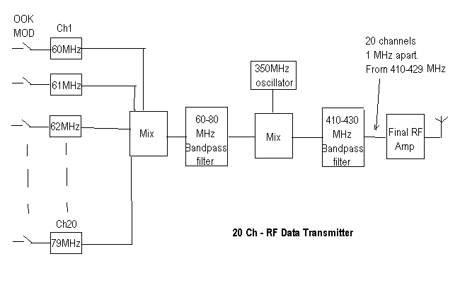
I'm working on wireless communication and faced some problem. I have to send wirelessly asynchronous binary signal, and I decided to do that using OOK modulation. When I use one resonator with frequency 433MHz everything works fine. But I have 10 channels and I need 10 different frequencies. Maybe some one know how can I generate them without using clk? For example 432MHz, 433MHz, 444MHz ect... Yes I know, there exist Volatage controlled oscillators, but they ar too expensive, so maybe there exist another possibilities? (Waring: My signal is asynchronous, so there are not bits length, switching from 0 to 1 and 1 to 0 is random and can be in any time moment).

Also How in practice is possible to get, for example, 64 OFDM cerrier frequencies? What is used? PLL?

Thanks.
 

I think you gave yourself a difficult task.
I would still go for the synchronous data stream- you can asynchronously transform the "wild" data onto sync data.
I do not think the 432 MHz band offers enough bandwidth for your ten OOK data channels.
I think there are 432,434, etc, SAW resonators available for small keychain oscillators. I would suggest trying to pull their frequencies but any external reactance usually degrades their Q.
For multichannel oscillators, you could use a synthesizer with a fast frequency-switching response. A similar frequency source you would need at the receiver. Filtering the sidebands will be tricky and crosstalk between the channels rather poor.
As you never mentioned any parameters of your input data, it is difficult to think about details. I have already advised you to try designing a two-channel system with a variable carrier frequency, then you could test it and see if the crosstalk is acceptable, adjust filtering, etc. Only by experiments you could see if such system can work.

The RC airplane or car models utilize well designed multi-channel data transmission. Maybe you could try that way, and use two-three such systems (304 channels each) on separate carriers summed, then all upconverted e.g. to 432 MHz band. Depends on that if you need a working system, or, something to play with for a long time. I prefer simple things, and many have already been invented.
 
You can expect that recent OFDM implementations are based on digital signal processing and wide band quadrature modulators.

Revieving your previous same topic thread, it seems to me that the questions you're posing now have been already discussed. https://www.edaboard.com/threads/226343/

There are pending questions related to the required signal bandwidth, I think.
 

You can design a simple VCO around 433MHZ with single transistor and you may multiply this design and then combine.
OFDM is more difficult task for you..;
 
This could be done like this. First make twenty oscillators, 100Khz apart above 5MHz. Modulte them individualy with your signal.Combine outputs of all frequency.Filter carrier and upper side band.You will get your 20 channels in 5-7MHz. Now modulate your uhf oscilator with this signal.The output will be above and below 5-7MHz of yor uhf carrier frequency. Filter upper side band for further amplification and output.You will get your 20 channels above 5-7MHz to your uhf carrier frequency.
This is same as fm and tv transmitters carry different audio and data channels on a single carrier. You have to choose frequencies to accomodate in legal bands.
 
Last edited:
Most people use a phase locked loop and a vco to do this. They do that because it is very frequency stable.

But if that is too expensive, a tunable resonator (something with a varactor diode) in the oscillator (instead of a crystal or saw resonator) will hop the frequency as a function of tuning voltage.
 
[/COLOR]
This could be done like this. First make twenty oscillators, 100Khz apart above 5MHz. Modulte them individualy with your signal.Combine outputs of all frequency.Filter carrier and upper side band.You will get your 20 channels in 5-7MHz. Now modulate your uhf oscilator with this signal.The output will be above and below 5-7MHz of yor uhf carrier frequency. Filter upper side band for further amplification and output.You will get your 20 channels above 5-7MHz to your uhf carrier frequency.
This is same as fm and tv transmitters carry different audio and data channels on a single carrier. You have to choose frequencies to accomodate in legal bands.

I didn't understund quite well. Can you please explain in little more details or with other words?
How you suggest me to make 20 oscillators, for example, Channel1:100kHz, Channel2:200kHz ... ... ChannelN:N*100kHz?

Also I like to mention, that my input signal ir binary and each channel have bandwidth about 1MHz. Signal switching frequency is 100-1000 Hz.

---------- Post added at 16:11 ---------- Previous post was at 16:06 ----------

Most people use a phase locked loop and a vco to do this. They do that because it is very frequency stable.

But if that is too expensive, a tunable resonator (something with a varactor diode) in the oscillator (instead of a crystal or saw resonator) will hop the frequency as a function of tuning voltage.

Like you can see VCO are very expensive: **broken link removed**
About 16 eur, and I I have to build 20 channels or 100 in future, then it will cost for me a lot of money. That is why I search alternatives. Can you suggest me real circuits or product with cheaper approach?

Thanks for helping :)

---------- Post added at 16:22 ---------- Previous post was at 16:11 ----------

I think you gave yourself a difficult task.
I would still go for the synchronous data stream- you can asynchronously transform the "wild" data onto sync data.
I do not think the 432 MHz band offers enough bandwidth for your ten OOK data channels.
I think there are 432,434, etc, SAW resonators available for small keychain oscillators. I would suggest trying to pull their frequencies but any external reactance usually degrades their Q.
For multichannel oscillators, you could use a synthesizer with a fast frequency-switching response. A similar frequency source you would need at the receiver. Filtering the sidebands will be tricky and crosstalk between the channels rather poor.
As you never mentioned any parameters of your input data, it is difficult to think about details. I have already advised you to try designing a two-channel system with a variable carrier frequency, then you could test it and see if the crosstalk is acceptable, adjust filtering, etc. Only by experiments you could see if such system can work.

The RC airplane or car models utilize well designed multi-channel data transmission. Maybe you could try that way, and use two-three such systems (304 channels each) on separate carriers summed, then all upconverted e.g. to 432 MHz band. Depends on that if you need a working system, or, something to play with for a long time. I prefer simple things, and many have already been invented.

I Can't use synchronous data stream and it can't be discussed anymore :)
Also I can use 2,4GHz, if 434MHz bandwidth will be too narrow for me...
Can you please explain what is keychain oscillators? I have few 434 MHz oscillators, I have already tested them, But I cant tune them to other frequencies, and this is my main problem. I need 20 different carrier frequencies. And you are right, when I try to tune them, the Q decrease and the tuining range is too low.

Can you please send me exact product - synthesizer with fast frequency switching? And i don't think that it would work becouse I have to send the data simultaneously for all channels, so I need stable frequency all the time, I just can't switch it.

Also maybe you have some circuits with RC transmission? Maybe there I could get deeper idea about this approach.

Thanks for your help :)
 
Last edited:

CC1101 cost around $2 and will easily do that. Try searching around for actual "low cost" ICs before spouting off on how they are "sooooo expensive"
 

72_1322815304.png


A transmittig section can be made on these lines using common components.
 
Last edited:
The 1st mix should be "power combiner"
 

Thanks everybody for your answers :)
 
Last edited:

I have read but can not find any information why a synchronous system not can be used. Because it adds delay? You seems to accept different kinds of delays related to bandwidth and such.
Time have always a certain resolution so from technical view can you use synchronous transmission, with enough clock rate.
The most complex system I know about in this range is a system with 2000 nodes, producing 40Gbps data, and need of correct timing within nS. All data are transferred in synchronous mode.
What system delay do you accept, and in case it is a very short delay, is it included RF link, such as distance between TX and RX?
As you have very low information density does it seems to be a vast of bandwidth. 20*1 MHz + some crosstalk protection.
Why not use one channel, 5 times as wide (¨5Mhz) and transfer 16 channel coded in 4 bits+status each time something occur, resulting in same range of error in time precision as 16 individual 1 MHz wide channels. It can be done CPU-less and as fast as bandwidth allows.
If the problem is to know when something actually did happen, is a more common way to poll a synchronous xx-MHz counter, and transfer a time-stamp, which avoids variations in time delay due to channel noise, coding/decoding bandwidth, distance between tx/rx...
 
I have read but can not find any information why a synchronous system not can be used.
The signal characteristic questions from the previous thread essentially haven't been answered. https://www.edaboard.com/threads/226343/#post991463

Unfortunately, you can neither determine the requirements for an old fashioned analog multi carrier frequency system nor for a state-of-the art digital solution without knowing it.

Like I mention several times before I can't use these chips, becous they are for synchronous systems. Please read this topic more cearfully to understand my problem. ;)
CC1101 and CC110L can be used for strictly asynchronous transmission by referring to an asynchronous serial option, that's provided for backward compatibility. The predecessor Chipcon/TI chips can anyway.

This picture looks nice, but it's quite theoretical. I need more explanation about practical implementation. For example how to generate 60, 61, 62 MHz.... Frequencies? Do I need 60 oscillators? Where I can get them? Any product code? Also suggest me please real commponent for first MIX? And what is Power Combiner? Can you give me please real product code for this purpuse? Also why I need 60-80MHz bandpass filter?

I agree to the circuit classification as "using common components", which is somewhat different from "quite theoretical", I think. You can e.g. assume a reference oscillator and a number of simple PLL chips for the individual oscillators. For the combiner, think of a resistor network. I guess, Tony mainly wanted to clarify that it's no mixer (which is a non-linear circuit in usual RF terms). And so on. But it's still a complex design, and the complementary receiver is even more.
 
I have read but can not find any information why a synchronous system not can be used. Because it adds delay? You seems to accept different kinds of delays related to bandwidth and such.

Yes it can be used, but I need to build asynchronous system!
 
Last edited:

I do not get your problem. You can set up 20 CC1101s and OOK each one of them asynchronously. They would each be phase locked to some central crystal, so they would not drift in frequency.

Normally people do this with a baseband DAC + Upconverter, or a 433 MHz PLL+I/Q modulator driven by 2 DACs.

Why do you need 20 frequencies? Are there 20 parallel bits coming in, or just one bit stream?
 

I do not get your problem. You can set up 20 CC1101s and OOK each one of them asynchronously. They would each be phase locked to some central crystal, so they would not drift in frequency.

I will repeat again. I can't use microcontroller and CLK, but CC1101 must have them both. And if it has a clk it can't send asynchronous data. If it is hard to understand I use this: **broken link removed** to encode my analog signal and switching from state +b to -b can happen at any time, there is no strict border where must me +b and -b, like in synchronous systems.

Why do you need 20 frequencies? Are there 20 parallel bits coming in, or just one bit stream?

There aren't bits, there are 20 binary outputs (20 streams), so I need 20 center frequencies. :)
 

i can send asynchronous data, but you do not seem open to suggestions, so good luck.
 

i can send asynchronous data, but you do not seem open to suggestions, so good luck.

I'm open very much, but You all the time trying to convince to use clock (CLK). If it is possible, then please read more about Time encoding machines and you will see that precision depends on time moment accurate mesurament, CLK is too inaccurate for my purpuse.
 

I will repeat again. I can't use microcontroller and CLK, but CC1101 must have them both. And if it has a clk it can't send asynchronous data.
Excuse me, but that's what people call ignorance. Related to CC1101 properties, you're just guessing, isn't it?

A microcontroller or similar system will be in fact needed to configure the CC1101, so if you don't like microcontrollers, that's a different problem. But it shouldn't be confused with the effects of time discrete signal processing.

It's good, that you explained your requirement of asynchronous signals transmission by referring to the async SD concept. Quantizing the digital output of course introduces an error signal. Instead of postulating infinite time resolution, one should however relate a possible quantizing or other timing error to the expectable SD timing resolution to get a serious specification for any kind of timing errors introduced by the digital channel. You possibly already did, but didn't mention a result.

P.S.: By the way, did you already analyze the effect of sending the "asynchronous" SD output through a bandwidth limited channel? It doesn't cause quantization, but correlation of consecutive signal edges with a superimposed non-linear characteristic. I can't survey the effect on the channel accuracy, but I doubt that it can be ignored.
 
Last edited:

Status
Not open for further replies.

Part and Inventory Search

Welcome to EDABoard.com

Sponsor

Back
Top