Continue to Site

Welcome to EDAboard.com

Welcome to our site! EDAboard.com is an international Electronics Discussion Forum focused on EDA software, circuits, schematics, books, theory, papers, asic, pld, 8051, DSP, Network, RF, Analog Design, PCB, Service Manuals... and a whole lot more! To participate you need to register. Registration is free. Click here to register now.

Variable frequency Sine wave Generator Problem

Status
Not open for further replies.

FMradio

Member level 3
Joined
Nov 24, 2009
Messages
58
Helped
0
Reputation
0
Reaction score
0
Trophy points
1,286
Location
Heaven
Activity points
1,672
Sir
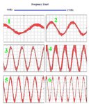
I made a Variable Frequency Sine Wave Generator that can vary frequency from 90 to 150Hz, its running fine, but the problem is that the noise in sine wave gets pronounced in between the certain frequency band as can be seen in screen # 4, below & above that band there is less distortion, what I should do to suppress that noise???

Drive.GIF

scope.JPG
 

Sir
I made a Variable Frequency Sine Wave Generator that can vary frequency from 90 to 150Hz, its running fine, but the problem is that the noise in sine wave gets pronounced in between the certain frequency band as can be seen in screen # 4, below & above that band there is less distortion, what I should do to suppress that noise???
It's some interference/spurious noise deteriorating the clean sine wave due to following expected factors:-
1,due to yours toggle/push push switch being dirty needs to be cleaned.
2,shielded wires inside needs to be checked.
3,if you provide the diagram,then the same can be checked thoroughly if some oscillator creating the trouble,however you yourself may check the oscillators producing the sine step by step by using the oscilloscope and moreover you should check the +B rail feeding to the circuit,
Regard,

sir
1) there r no toggle/push push switches just a Variable Resistance.
2) do i need sheilding???
3) it has just one Crystal in FPGA Card.
4) Batt+ is OK

@ ch wazir
Lets wait for the Experts & see what they say about that
 

Hi FMradio,

for my opinion, it does not look like noise. Instead, I think it is an indication of spurious high frequency oscillations.
In this context, it would be interesting to see the circuitry of the oscillator.
 

It's far from obvious how you achhieved a variable frequency oscillator with a FPGA. In any case, you should check if the base band signal is a clean sine. Apart from modulation signal quality, it may be also a problem introcduced by your PWM modulator. What's the numerical resolution of the PWM setpoint, what's exactly the implemented PWM scheme?

Besides possble PWM problems, the output signal quality will of course depend on frequency and load impedance, according to the filter parameters.
 

Largest Ripples occure around d=50% .(IMO its not noise and just more ripple)
What is your filter for removing the carrier frequency?
 

Largest Ripples occure around d=50% .(IMO its not noise and just more ripple)
What is your filter for removing the carrier frequency?

Yup the LC filter is to remove the High frequency Components
 

I guess you mean 800uH.
Anyway if you want a very clean waveform a simple LC doesn't work.
Try notch filters+ low pass filter to remove 10khz carrier.
I have passed filter design course 15 years ago but you can search it!
 

Try some filter design software. I think I would go with 5 or more pole Chebyshev filter tuned to around 500 Hz.
 

Status
Not open for further replies.

Similar threads

Part and Inventory Search

Welcome to EDABoard.com

Sponsor

Back
Top