Vermes
Advanced Member level 4
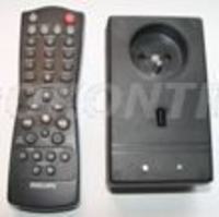
The whole system is controlled by AVR microprocessor – Attiny2313. The system is powered directly from the power grid 230V, realized by the power supply without a transformer. TSOP1736 was used as infrared receiver from the remote control. Very simple user interface was implemented using one button and one LED for easy programming of the system. Printed circuit board was designed for mounting in the plastic housing Z-27.
The main purpose of construction of this device was to increase the convenience of using electrical appliances, in which there is no possibility of switching on and off by remote control.
Assumptions:
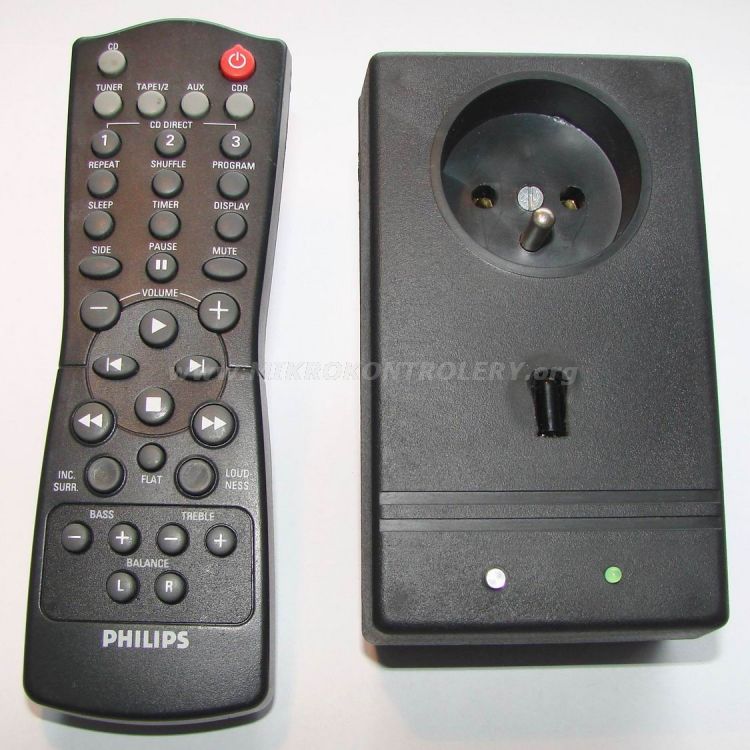
The most important assumption was to switch AC circuits on and off with an efficient voltage of 230V by using commonly available remote controls with encoding standard RC5 and using two of their buttons. Most importantly, everyday use remote controls for electronics can be used. It is worth remembering that only those buttons, which are not used everyday, should be used for this purpose (so that there was no situation where, for example, while changing the channel on the TV, lighting in the room is being switched on).
The project is of simple construction and uses cheap and readily available electronic components. All electronic components are hole type and the board is one-side printed.
Another assumption concerned the programming of on and off button. It was to be implemented as simply as possible, using a single button and one LED.
Battery powering the system was not considered, because of the relatively large continuous current consumed by the relay coil during switching. Also there is no internal transformer power because of its large size, weight and price. According to the assumptions, the system was to be powered by a transformerless power supply directly from the grid of 230V effective voltage.
Microcontroller Attiny2313
Minimum conditions that the microprocessor has to meet:
- 2kB flash memory
- one external interrupt
- one 8-bit counter
- one 16-bit counter
- four I/O lines
- power supply 5V
- compact design
- easy access
- low price
- 2kB flash memory
- 128B EEPROM
- 128B SRAM
- two external interrupts
- one 8-bit counter
- one 16-bit counter
- 18 I/O lines
- power supply 2,7V-5,5V
- medium size housing PDIP-20
- available in almost all electronic stores
Power:
As the remote control system was to be simple and not require additional power from the outside, it was decided to apply a transformerless power supply. This solution involves a number of problems. The most important are: no galvanic separation of electronic circuits from the power grid and very limited current capacity.
Main elements of the power supply are polypropylene capacitor C4 with a large capacitance (1uF), current limiting resistor R1 with a value of 220ohm and minimum power of 1W and rectifier bridge. Large amounts of heat are secreted on the resistor R1 due to losses caused by current flowing directly from the power grid. Two resistors R2 and R3 with a resistance of 47kohm connected in parallel with capacitor C4 cause its discharge after disconnecting from the mains, what increases the safety of using the system. If the unloading resistors would not be used after disconnecting the system and touching the pins of power plug, user would be struck by a slight shock, which does not necessarily have to be dangerous for life or health, but cause an unpleasant feeling.
Another important element is the rectifier bridge made up of four rectifier diodes D1-D4 1N4004 type in Gretze system. Just beyond the rectifier bridge, there is a capacitor stabilizing capacity (C2) 1000uF and Zener diode D5 with rated voltage of 12V. At this point, the output voltage is constant with a value of about 12V. The relay is powered directly from this point. 12V relay was used to reduce current consumed by the entire system.
For the purpose of microprocessor power, the voltage stabilizer 78L05 in housing TO92 (Fig.1a) was used. It was marked as IC1 on the schematic diagram. At the assembly scheme, instead of the stabilizer 78L05 there is a drawing of housing TO220, it is a deliberate procedure that allows the use of a stabilizer 7805 in housing TO220 (Fig. 1b). The only difference between stabilizers 7805 and 78L05 but housing is a current efficiency, which is respectively 1A and 100mA (0,1A). For the purpose of this project, a stabilizer with current 100mA is sufficient. According to the note sheet of the system, a condenser filtering the noise of power with a value of 100nF should be added after the stabilizer (it is capacitor C3 on the diagram).
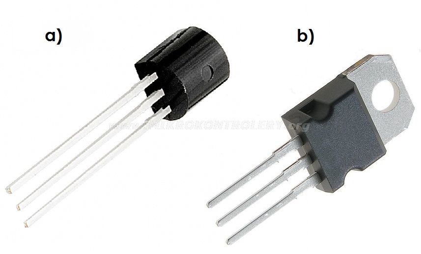
Fig. 1. Housings: a) TO92; b) TO220
Infrared receiver:
The signal from the remote control is sent as an infrared rays from transmitter diode. The signal is modulated, what means that the high state is sent as a series of rectangular pulses with a frequency of 36kHz. This method of transmission reduces power consumption by the transmitting diode, because it does not work all the time of transmission, but it depends on the fulfillment of the modulated signal. Demodulate the signal (transition from modulated signal with a frequency of 36kHz to a continuous signal) is provided by a circuit infrared receiver TSOP1736. Continuous not modulated signal is obtained at the circuit output. In a state where any signal is not sent, high state (+5V) appears at the output. While the pulse is sent, there is low state at the output. Negation of the output signal allows the reduce of the signal distortions. In the manufacturer's note, you can read that to proper work of the system, a resistor limiting the current powering and voltage filtering capacitors should be used. They are respectively R5 (100ohm) and C1 (4,7uF) on the schema.
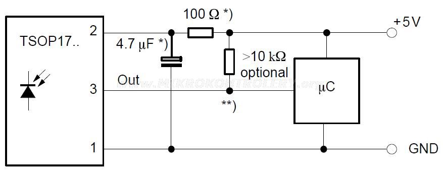
Fig. 2. Way to connect the integrated infrared receiver TSOP1736 to the microprocessor by the manufacturer's note.
Programming the remote control buttons:
Easy programming buttons on/off was carried out with one button microswitch type and one LED. The button is connected to the mass and directly to PD6 input of microcontroller Attiny2313. This input is programmatically “pulled” to the supply voltage, so when the button is not pressed, high state remains at the PD6 input. When the button is pressed, low state appears at the PD6 input, what is interpreted by the microcontroller as pressing the button. To allow pressing a button on the PCB, a button extension (Fig. 3) has to be made. It was made of aluminum rod on lathe. Cathode LED is connected to the mass of the system, and the anode through the resistor to the microcontroller output PD5. High state at PD5 output causes the LED lights, and low state disable the LED.

Fig. 3. Aluminum extension of the button.
Programming is done by pressing and holding the button for 3 seconds. The LED starts to blink slowly, then refer the remote control to infrared receiver and press the chosen switching button on the remote control. After properly receiving the data frame, LED lights up permanently for 2 seconds and the relay is switched on. Then the LED starts flashing faster, which means waiting for pressing the selected button of switching off on the remote control. Similarly, after receiving the correct data frame from the remote control, the LED stops flashing and lights steadily for 2 seconds and is turned off, then the relay is disconnected. After this process, programming the buttons is completed and you can use the device. This version does not provide writing data to non-volatile EEPROM memory. After each shutting down the system, you must re-program the buttons on and off.
PCB design:
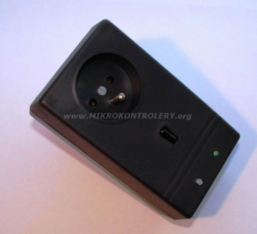
Schematic diagram and PCB were designed in Eagle. In Figure 4 there is a view of electrical wiring diagram (schematic diagram). In addition, Figure 5 shows view of copper tracks mosaic on the PCB and assembly diagram in Figure 6. The board was designed specifically for plastic housing type Z-27 (Fig. 7).
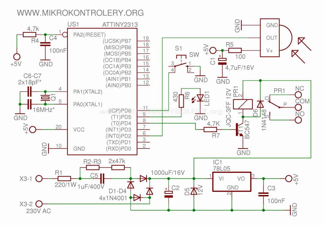
Fig. 4. Schematic diagram of remote control system.
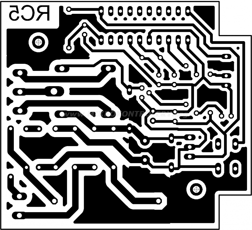
Fig. 5. Scheme of copper tracks mosaic (resolution 600dpi).
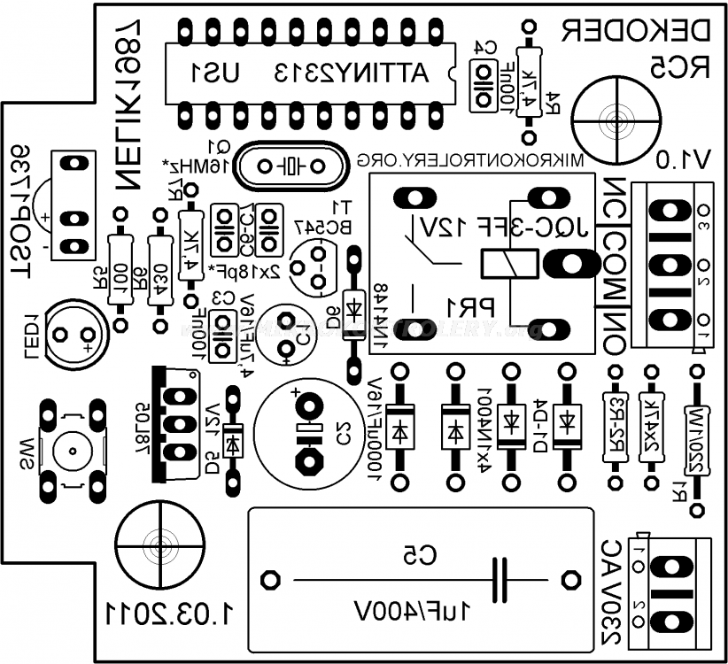
Fig. 6. Assembly diagram (resolution 600dpi).

Fig. 7. Universal plastic housing Z-27.
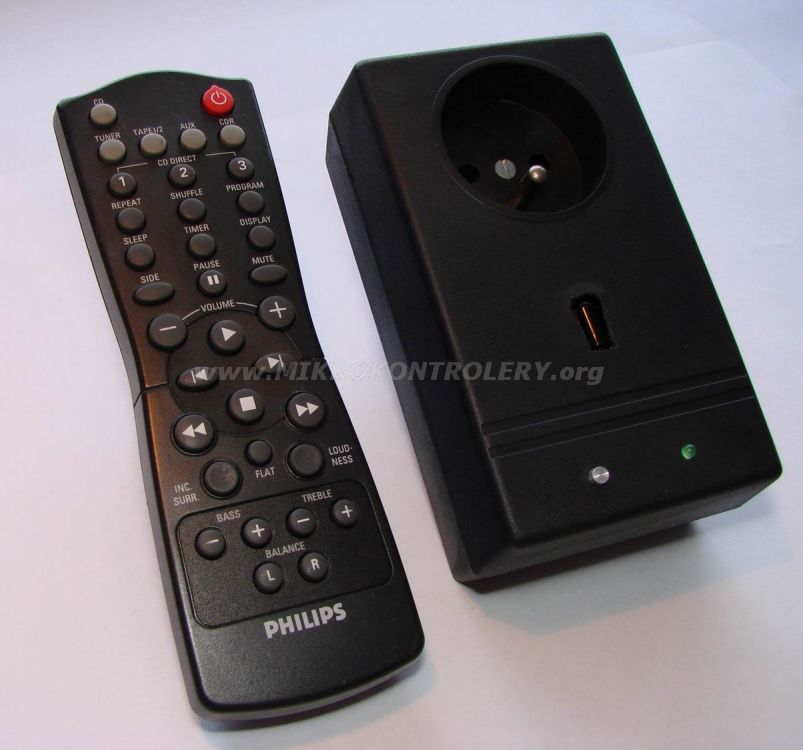
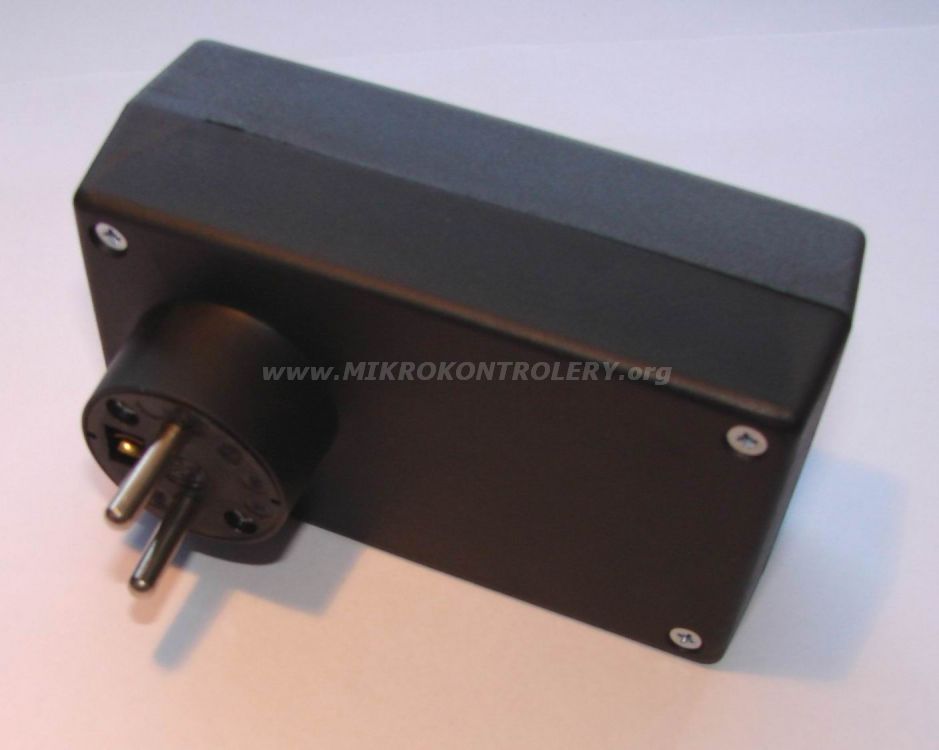
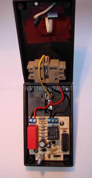
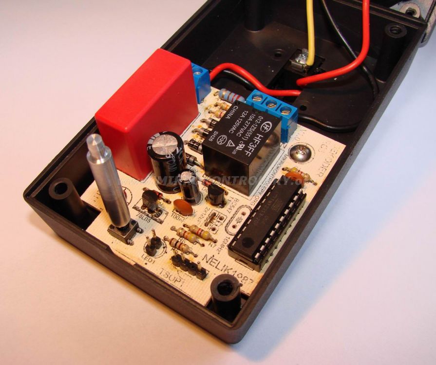
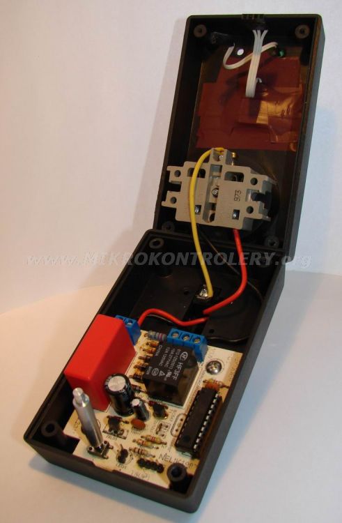
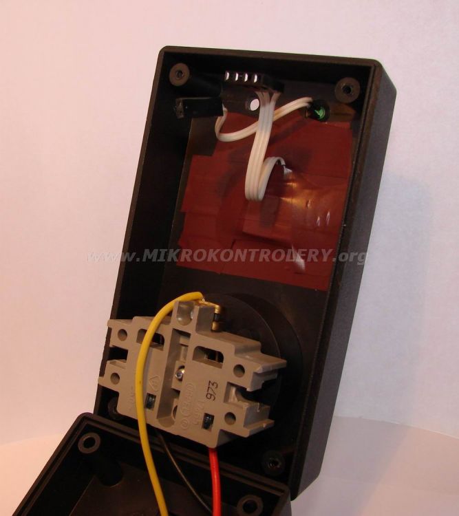
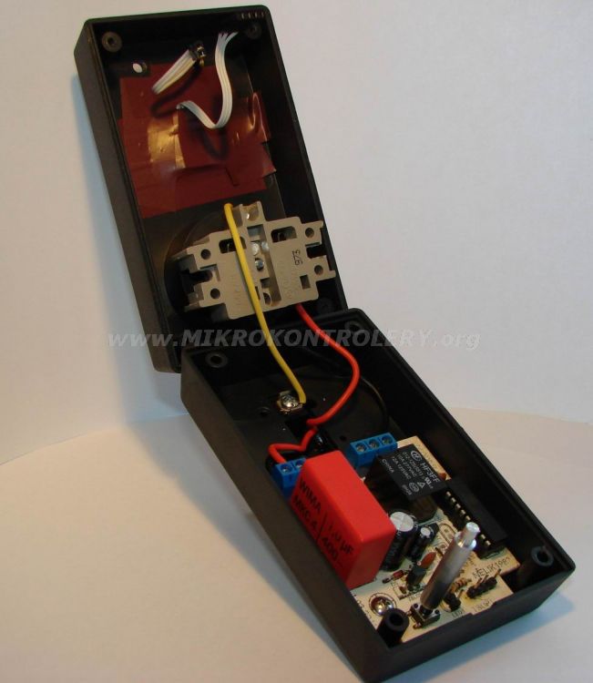
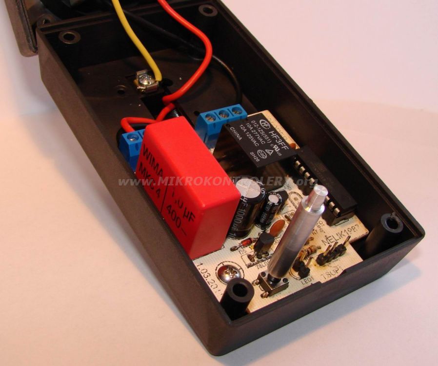
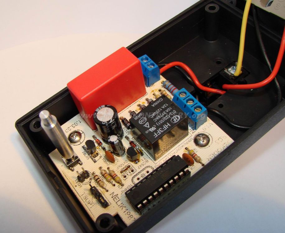
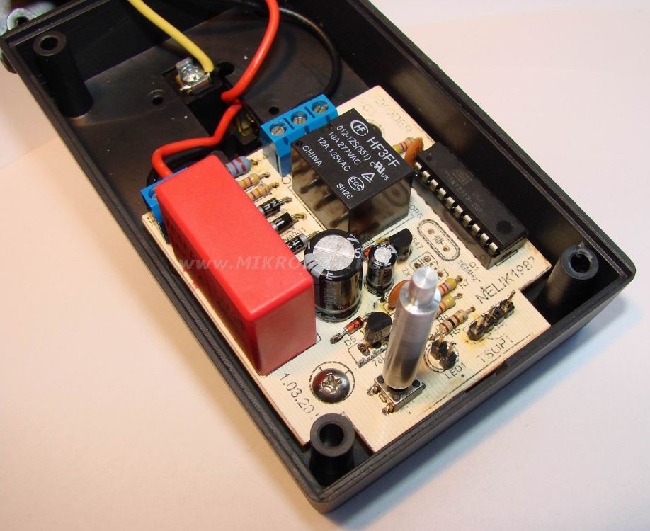
Pictures of the system:
Link to original thread – Zdalne sterowanie na podczerwień pilotem RC5