Vermes
Advanced Member level 4
Technical assumptions:
- timing (clock, calendar)
- temperature and humidity outside measurement (flat)
- temperature inside measurement (flat)
- atmospheric pressure measurement
- use of low-cost digital I2C sensors
- use of Atmega8 and Bascom compiler
- ability to program the device without removing Atmega8 board
There may be some mistakes in the code, so it is recommended to carefully analyze.
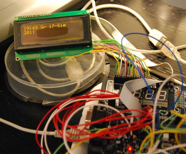
PC keyboard was used to set the clock.
The original idea was to use digital sensors of air humidity with I2C communication. SensironSHT11 type humidity sensor even though it uses digital communication and has the SDA and SCK pins, it is not compatible with the I2C. Fortunately, it turned out that the procedure for operating this transmitter is available on at LINK. Only few minor changes were introduced to reduce code size and instruction “Bitwait” was also changed. The purpose was that the device works without the sensor plugged.
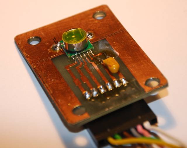
The sensor is miniature, adapted to surface soldering. The board and elements cooperating SMD were bought with the sensor.
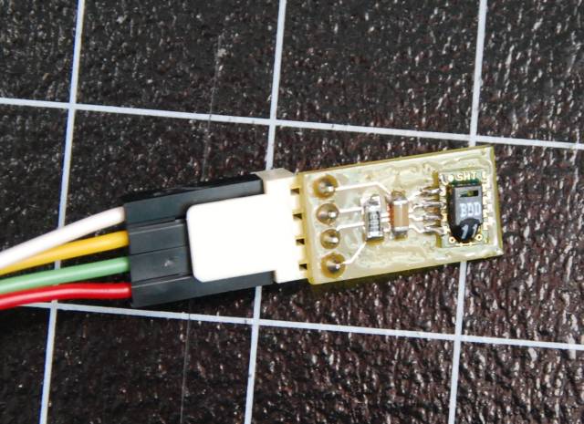
SHT11 measures the humidity and temperature inside the apartment. The temperature – because it has an integrated digital thermometer, also used to compensate the influence of temperature on humidity indication.
To protect the sensor against mechanical damage, it was installed on an aluminum tube, as shown in the following photo. That is why the temperature measurement is consistently overestimated by about 0,5 degrees Celsius.
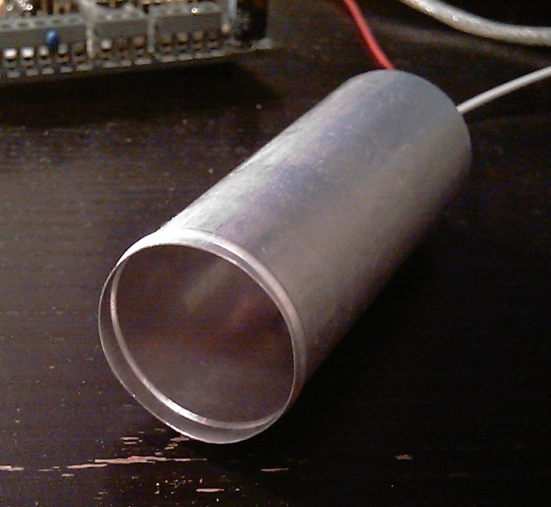
The tube was open on one side, and on the other side the cables were derived. Unfortunately, that affected the quality of measurement, so the sensor has to be installed without the cover.
A popular thermometer Dallas DS18B20 was plugged to the Tesla board. It measures temperature outside the flat. It uses 1Wire protocol and allows communication to a significant (several meters) distance.
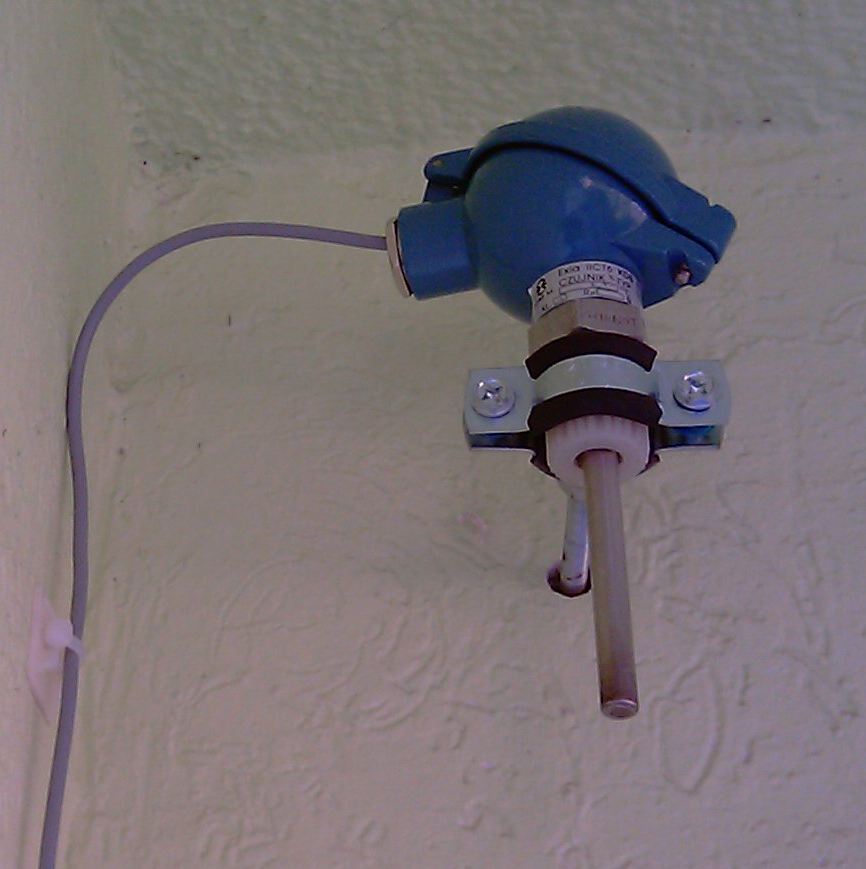
The sensor's housing was made of an old PT100. Previously, it was smeared with paste to the processors, then the tube was sealed with hot glue. Multiple comparison of the indications to reference thermometer (TES1311A) showed the correctness of such a solution.
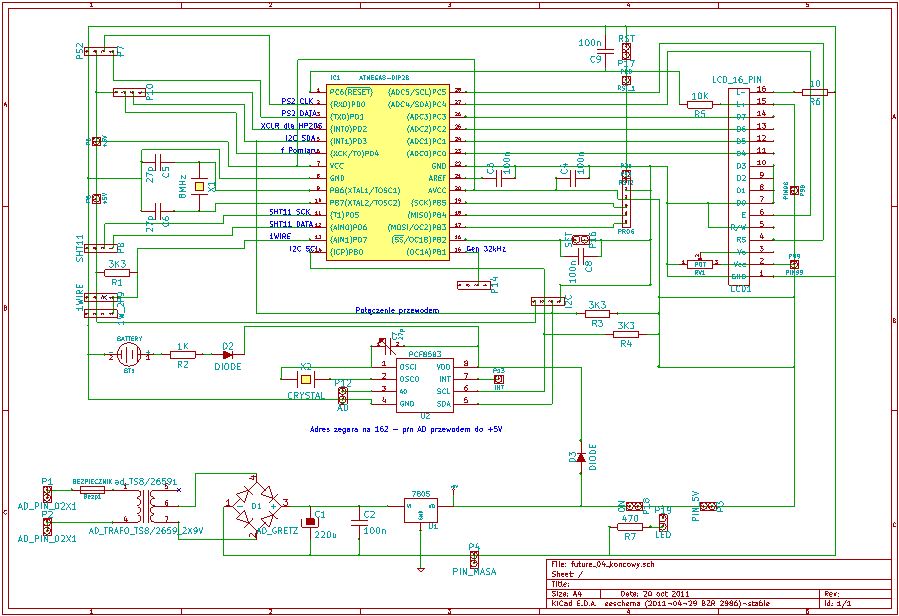
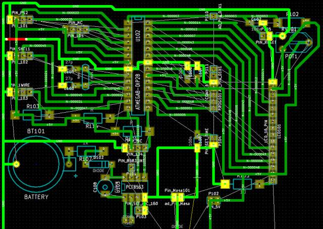
Schema of the board was drawn and the plate projected in KiCad. List of connections was generated also in this program. Mini-tutorial on **broken link removed** may be helpful.
Iron method was used to make the board instead of manual drawing.
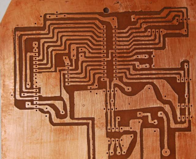
In places when toner did not stick, the paths were supplemented with a permanent marker.
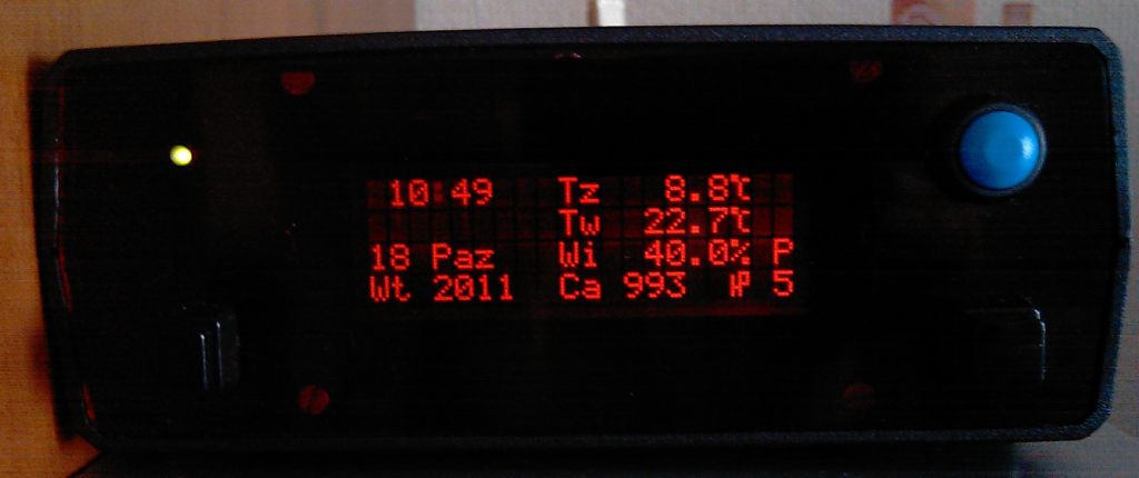
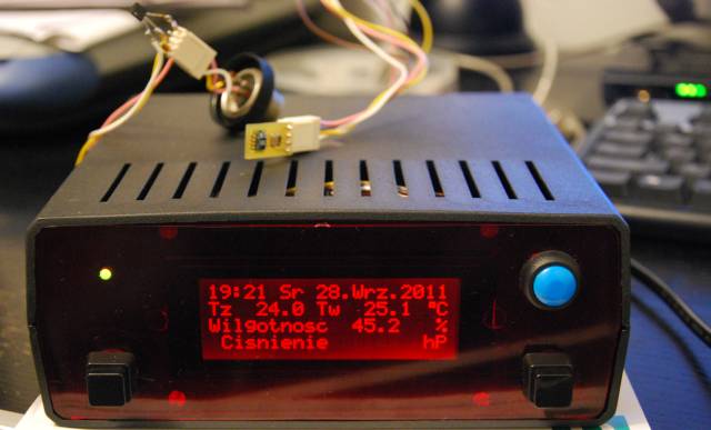
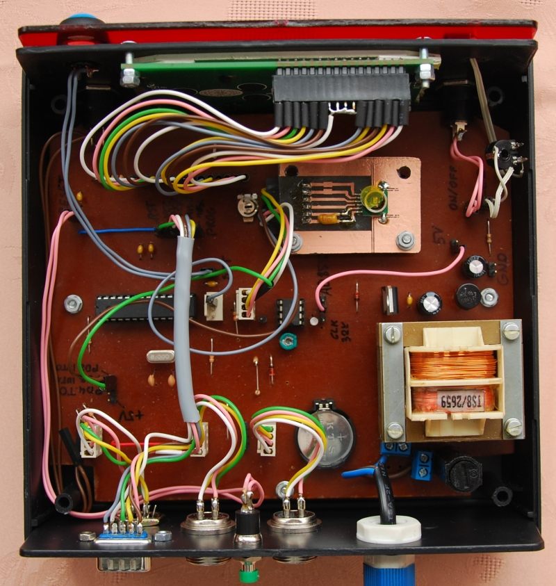
The device was closed in a plastic housing Z-1A. The front panel has a LCD 4 display, 20 characters in lines and switches:
- ON/OFF
- SetTime – enables the entry to the procedure of setting the time
- Measurement – determines the time between following measurements – 1min or 5min
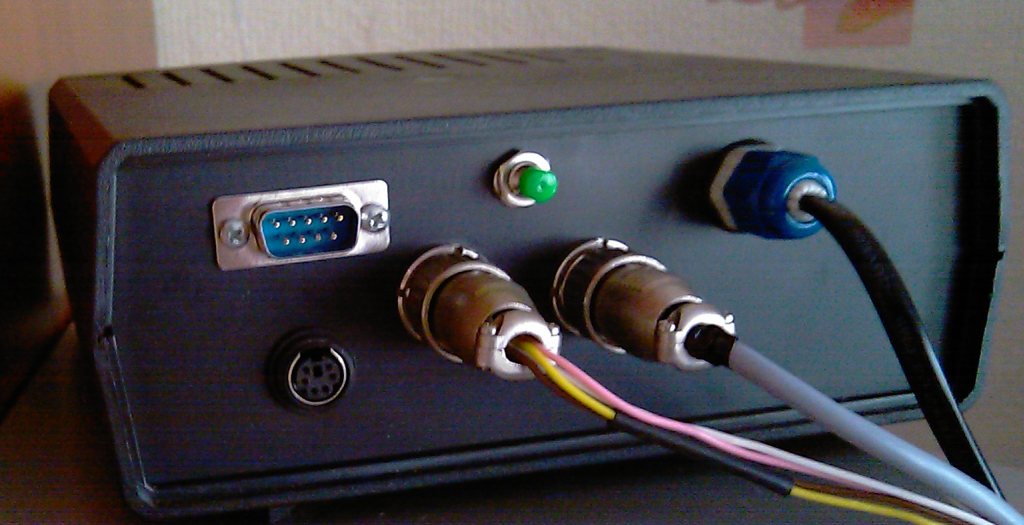
The rear panel includes:
- PS2 keyboard socket
- socket for connecting the SPI programmer (RS232 connector)
- Reset button
- socket for connecting the sensor STH11
- socket for connecting the sensor DS18B20
- choke on 230V power cable
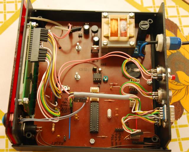
A cheap pressure transducer with good technical parameters was HopeRF HP02S. It was connected to I2C rail. The sensor needs signal of 32768Hz (MCLK) and control signal (XCLR). Atmega8 has internal timers, with use of which the generator of such type can be done. One path from OC1A on the PCB was cut. I2C rail was moved to other free output. XCLR control was led from another output. Because the microcontroller output was led on the top side of the board, HP20S sensor was correctly connected by cables.
Generator about 32kHz for HP20S
Config PinB.1 = Output
Config Timer1 = Timer, Clear Timer = 1, Compare A = Toggle, Compare B = Disconnect, Prescale = 1
Compare1a = 242
The sensor ought to be calibrated (by for example Beamex MC5).
The program was written in BASCOM.
To reduce the size of the code, it is good to resign from the use of the “Fusing”. In this place, a subprogram - formatter measurement results to a standard form should be prepared. Also, replacing multiplication by integers which are power of 2 to bit transfers is a good idea. Also important was that the program functioned well after disconnecting the sensors from the device. For this purpose, the global variable “Err” was used.
Link to original thread (attachment) – Barometr, wilgotnościomierz i termometr w jednym