Continue to Site

Welcome to EDAboard.com

Welcome to our site! EDAboard.com is an international Electronics Discussion Forum focused on EDA software, circuits, schematics, books, theory, papers, asic, pld, 8051, DSP, Network, RF, Analog Design, PCB, Service Manuals... and a whole lot more! To participate you need to register. Registration is free. Click here to register now.

Unipolar Stepper Motor Controller (Schematic issues)

Status
Not open for further replies.

kodex

Newbie level 4
Joined
Nov 8, 2011
Messages
7
Helped
0
Reputation
0
Reaction score
0
Trophy points
1,281
Location
Milwaukee, WI
Activity points
1,342
Hello all,

I am attempting to construct my own small CNC mill using the circuitry found here: Easy to build CNC Mill Stepper Motor and Driver circuits

I have one axis of the machine wired up, but I'm stuck. For protecting the motor, the gentleman who designed it used a small light bulb in place of a resistor. I would prefer to just use a resistor as I don't have access to the same type of bulbs he used. I'm just at a loss as knowing what type of resistor to select. How do I figure out many ohms/watts it needs to be rated for?

Thanks,
Steve
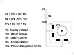
 

You can calculate needed values
this way................
Stepper_Rserial.jpg
 

Thank you!

I'm thinking that I will use the motor listed here: **broken link removed**

It is 12v and has a current rating of 0.4a.

12v power supply - 12v motor / 0.4 amps = 0

If I am using a 12v power supply, does this mean that I do not need a resistor at all?

-Steve
 

Yes.
Motor data gives
Voltage : 12V
Current : 0.4A
Resistance : 30 ohm

If we check the short-circuit current ; it is : I = U/R >> 12V / 30 ohm = 0.4 A
this means series resistor is not needed.

KAK
 

Awesome, thank you again for the help!

If you would be able to look at this schematic for the controller I am building: https://www.instructables.com/files/orig/FX6/0KDG/F6B7SXUN/FX60KDGF6B7SXUN.pdf

I've got everything wired up as shown. According to the instructions, "the resistor R1 drops the voltage, the Zener diode regulates it to 6.2 volts and the capacitor C1 filters out any noise from the motor, and this voltage powers the two IC's." I just don't get how the Zener Diode is supposed to do anything when it looks like it's out in the middle of nowhere? Should it not be between R1 and the ICs instead?

-Steve

---------- Post added at 18:32 ---------- Previous post was at 18:11 ----------

I set up R1 and the Zener on my breadboard and busted out my voltmeter (~12v source). I find 10.6v between the two components. So, the ICs aren't getting the 6.2v they're supposed to according to the description (link in my first post). Any suggestions on how I should rearrange things?

-Steve
 

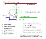
Power supply at point PL6 must be +12Vdc, as we calculated yesterday.
Then zener regulator drops voltage to 6.2Vdc if load current is lower than 5.8mA.
Look calculation.................
Stepper_Zener_Regu02.jpg

If higher current at 6.2V is needed , zener circuit must recalculate. ( Smaller value R1)
or use cheap 7805 or 7806 regulator and diodes to get 6.2...7Vdc

How to calculate zener regulator
Zener Diode Calculator

Electronics Tutorial about Zener Diodes
Zener Diode Tutorial

...................................................................................

Simple Unipolar Stepper Motor Driver Circuit
Unipolar Stepper Motor Driver Circuit - Northwestern Mechatronics Wiki

L297 Datasheet
price about 3...4$

Whatkind of NC-controller you are thinking to use.
3- or 4-axis ?
USB, RS-232 or parallel port type ?
 
Last edited:

    V

    Points: 2
    Helpful Answer Positive Rating
I'm looking to drive a 3-axis machine, so I figured I would use 3 of these boards to accomplish that by driving the directly from the parallel port and powering it all with a ATX power supply from an old computer. The data sheets say these chips draw less than 1mA each, so it shouldn't be a problem, I think, as each counter/decoder pair will have its own zener diode.
 

I have used a number of different CAD/CAM packages in my day, so I'm sure I'll be able to find something that works for me on that end.

However, I have another question. I see that a number for people use 24-volt, 36-volt, or even 40-volt power supplies to power their steppers. If I need to drop the voltage to the motor with a resistor anyway, is there any benefit for me in using say a 24-volt instead of a 12-volt?
 

Steppers should be sized according to published torque curve, which is specified by the manufacturer at particular drive voltages
or using their own drive circuitry.
The rated voltage will produce the rated winding current at DC: but this is mostly a meaningless rating, as all modern drivers are
current limiting and the drive voltages greatly exceed the motor rated voltage.
A stepper's low speed torque will vary directly with current.
How quickly the torque falls off at faster speeds depends on the winding inductance and the drive circuitry it is attached to,
especially the driving voltage.

ie if your driver has current limiter, you can go a bit higher supply voltage and get more torque in higher rpm´s.
but i think, using resistance and motor in serial helps nothing, it only waste energy of power supply and generate unwanted heat.
 

This is working card and software for newer PC´s and Win7


CNC USB Controller Mk1 - 4-axis

25 kHz maximum step frequency
3 digital outputs (flood, mist, spindle)
12 us minimum pulse width
manual jog input keys for all axes
limit keys for all axes
control external devices with I2C protocol


CNC USB Controller software is specialy designed to work with controller.
Features and specifications:

USB (V2.x) from PC/Laptop running Windows XP, Vista or Windows 7 (32 bit or 64bit)
motor driver connector pin-out is compatible with 10 pin open source interface
controller works with most step/dir motor drivers available on the market
buffered IO for maximum performance
advanced interpolation algorithms
start, stop, pause and resume execution of program on your machine
standard RS274/NGC G-code (EMC2 compatible)
advanced G-codes - G40, G41, G42 (Cutter Radius Compensation) supported
advanced G-codes - G43, G49 (Tool Length Offsets) supported
advanced G-codes - G54, G59.3 (Coordinate System Origins) supported
tested with SolidCAM, MasterCAM, ArtCAM, Vectric, ... generated G-code
Profili 4-axes and 3-axes G-code supported
import toolpath from DXF files
import toolpath from PLT/HPGL files
import toolpath from image files
import toolpath from NC-Drill (Excellon) files
import toolpath from Gerber (RS-274X) files
toolpath simulation
automatic homing procedure
advanced toolchange procedures
export toolpath to G-code
export toolpath to DXF
SDK (software developers kit) is available
works on MacOS X (Snow Leopard 10.6.3) with virtual machine emulating Windows XP SP3

CNC USB controller
 

I suppose I should have looked before I leaped. I bought three of these motors. I also bought **broken link removed**. I am told that because of the high winding inductance of the motor, the PSU will not have enough power to drive these motors.

Is this true? If so, what sort of ratings would be required to drive them? And I would really like to spend as little as possible to have all my circuitry going, so are there any cheaper boards out there that you would recommend? If my PSU is enough, would either **broken link removed** board or this board be compatible with my motor?

Again, Thank you for all the help!
 

I am told that because of the high winding inductance of the motor, the PSU will not have enough power to drive these motors.
An important parameter in the selection or design of the driver is the current it sends through the coils of the motor.
The current specified for the motor is the maximum current that is allowable per phase. To avoid damage to the
motor it is decisive to ensure that this current is not exceeded. This implies that the current of the drive must be
restricted to this or any lower value. Many drives allow limiting the current either by potentiometer, DIP switches or
by soft setting for example through the indexer. As step motors tend to run hot it is advisable to use a current that is
as low as possible while still maintaining reliable operation of the application. This means that in many applications
the actual maximum phase current used will be lower than that allowed by the motor manufacturer. This will help to
maximize the lifetime of motor and driver hardware.

The higher the output voltage from the driver, the higher is the level of torque versus speed. You can think of the
voltage as the driver of the current. The higher the voltage, the faster will the current in the windings reach its new
target value from one step to the next. Therefore it is conceivable why a higher voltage will result in better speed
performance.
The torque versus speed behavior varies strongly across stepping motors. Parameters such as the inductance of
the coils and their resistance play an important role. The higher the inductance, the worse the performance will be at
higher speeds.
stepper_torque_speed_volt.jpg
The voltage applied to the step motor should be higher than the rated motor voltage. It is common to use a voltage
that is 3 to 25 times the rated motor voltage. As an example, for a motor that is rated at 3.7V, supply voltages in the
range of 11V to 92V are typical. Again, the higher the voltage, the better the performance will be.
Note that the rated motor voltage does not represent the maximum voltage that can be applied to the motor. In fact,
the motor will normally not operate properly at the rated motor voltage.
Unregulated power supplies are best suited for step motor applications.
The current capability is another key parameter in selecting an appropriate power supply. The current rating is
determined by the choice of motor and the stepping mode you are planning to use it in. Full step mode, where both
phases are on all the time at maximum current, requires more current than microstepping modes. Also, the current
draw strongly depends on the voltage. The higher the voltage, the less current will be required from the power
supply to achieve a given phase current in the windings of the motor.
Typically a power supply capable of delivering ½ or more of the peak phase current should be sufficient. For
example, if you are using a motor with a maximum phase current of 4A per phase and assuming the drive is set to
this maximum value, a power supply capable of delivering 2A or more will be adequate in most applications.
When connecting several drives / motors to one power supply, the current draw for all drives need to be added
together to yield the requirement for the power supply.

Your motor inductance/phase is 60mH >> this is high value >> for higher speeds motor needs higher voltage
- high supply voltage needs active current control in driver stage. ( series resistor only is not good enough in this case )
- On the other hand , motor in holding state (stopped) current should not be over 0.4A >> motor voltage = 12Vdc
Depending on the motor driver and needed max. speed motor supply voltage can be in range 24....48Vdc and even higher ??
Your motor current/phase is 0.4A >> so for 3 motors needed power supply current is 1.2...2.0A

quotations from : Stepper Motor System Basics (Rev. 5/2010)
**broken link removed**
 

I don't see a suitable method to operate the said unipolar 12V stepper 42BYGH302 with a high voltage chopper driver to achieve higher speed. All common PWM driver are using bipolar motors.
 

Status
Not open for further replies.

Part and Inventory Search

Welcome to EDABoard.com

Sponsor

Back
Top